7 layers OSI model is a short name for the Open Systems Interconnection (OSI) reference model for networking. This theoretical model explains how networks behave within an orderly, seven-layered model for networked communication. The OSI model isn’t specific to a protocol suite and can be applied to most networking protocols past and present.
Although the OSI model isn’t specific to one protocol suite, it’s the standard model for discussing, teaching, and learning the field of computer networking. It’s unlikely you’ll have a course in networking that doesn’t at least mention the OSI model.
Who created the 7 Layers OSI Model?
The OSI Model was developed by the International Organization of Standardization, aka ISO, in 1984. It is a 7 layer architecture with each layer having specific functionality to perform.
However, the model was first defined in raw form in Washington, DC in February 1978 by Hubert Zimmermann of France, and the refined but still draft standard was published by the ISO in 1980. (source Wikipedia)
But what is the OSI Model exactly?
OSI is an architectural model for open networking systems that was developed by the International Organization for Standardization (ISO) in Europe in 1974. The Open Systems Interconnection (OSI) reference model was intended as a basis for developing universally accepted networking protocols, but this initiative essentially failed for the following reasons:
- The standards process was relatively closed compared with the open standards process used by the Internet Engineering Task Force (IETF) to develop the TCP/IP protocol suite.
- The model was overly complex. Some functions (such as connectionless communication) were neglected, while others (such as error correction and flow control) were repeated at several layers.
- The growth of the Internet and TCP/IP «a simpler, real-world protocol model» pushed the OSI reference model out.
- The U.S government tried to require compliance with the OSI reference model for U.S. government networking solutions in the late 1980s by implementing standards called Government Open Systems Interconnection Profiles (GOSIPs). This effort was abandoned in 1995, however, and now few real-world implementations of OSI networking protocols exist outside of Europe.
The 7 Layers OSI model (that’s how I like it to call) is best seen as an idealized model of the logical connections that must occur in order for network communication to take place. Most protocol suites used in the real world, such as TCP/IP, DECnet, and Systems Network Architecture (SNA), map somewhat loosely to the OSI reference model. The OSI model is a good starting point for understanding how various protocols within a protocol suite function and interact.
OSI is an abstract model
The development of OSI standards, i.e. standards for the interconnection of real open systems, is assisted by the use of abstract models. To specify the external behavior of interconnected real open systems, each real open system is replaced by a functionally equivalent abstract model of a real open system called an open system. Only the interconnection aspects of these open systems would strictly need to be described. However, to accomplish this, it is necessary to describe both the internal and external behavior of these open systems. Only the external behavior of open systems is retained for the definition of standards for real open systems. The description of the internal behavior of open systems is provided in the Basic Reference Model only to support the definition of the interconnection aspects. Any real system which behaves externally as an open system can be considered to be a real open system.
External reference: Open Systems Interconnection – Basic Reference Model: The basic model
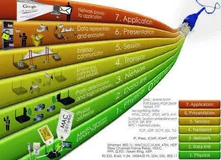
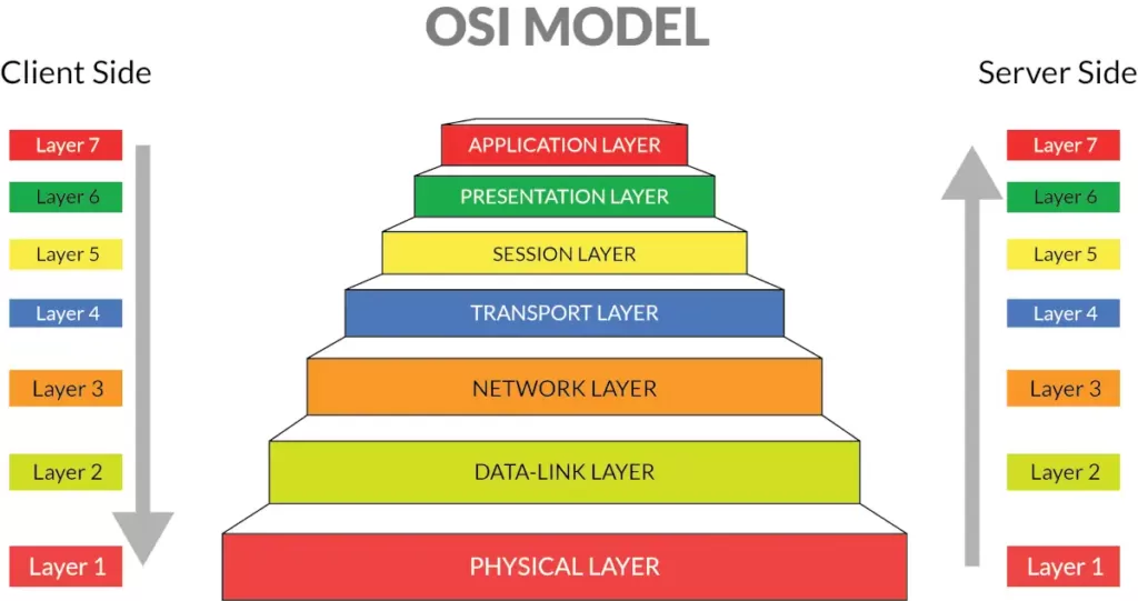
7 Layers OSI Model
Layer 1 – Physical Layer
Defines network transmission media, signaling methods, bit synchronization, architecture (such as Ethernet or Token Ring), and cabling topologies. Defines how network interface cards (NICs) interact with the media (cabling). Read more
Layer 2 – Data-link Layer
Specifies how data bits are grouped into frames, and specifies frame formats. Responsible for error correction, flow control, hardware addressing (such as MAC addresses), and how devices such as hubs, bridges, repeaters, and Layer 2 switches operate. The Project 802 specifications divide this layer into two sublayers, the logical link control (LLC) layer, and the media access control (MAC) layer. Read more
Layer 3 – Network Layer
Defines logical host addresses such as IP addresses, creates packet headers, and routes packets across an internetwork using routers and Layer 3 switches. Strips the headers from the packets at the receiving end. Read more
Layer 4 – Transport Layer
Sequences packets so that they can be reassembled at the destination in the proper order. Generates acknowledgments and retransmits packets. Assembles packets after they are received. Read more
Layer 5 – Session Layer
Defines how connections can be established, maintained, and terminated. Also performs name resolution functions. Read more
Layer 6 – Presentation Layer
Translates data to be transmitted by applications into a format suitable for transport over the network. Redirector software, such as the Workstation service for Microsoft Windows NT, is located at this level. Network shells are also defined at this layer. Read more
Layer 7 – Application Layer
Interfaces user applications with network functionality, controls how applications access the network, and generate error messages. Protocols at this level include HTTP, FTP, SMTP, and NFS. Read more
Data presentation and session management not really necessary
Data presentation and session management are important concepts, but it has not proved necessary, or even particularly useful, to make them into true layers, in the sense that a layer communicates directly only with the layers adjacent to it. (SSL/TLS, 22.10.2 TLS, might be an example of a true layer providing encryption; applications read and write data directly to the SSL/TLS endpoint, which in turn manages the TCP connection.) Generally what happens is that the Application layer manages its own Transport connections, and then reads and writes data directly from and to the Transport layer.
Conventional libraries for presentation actions
The application then uses conventional libraries for Presentation actions such as encryption, compression, and format translation. Similarly, applications typically implement their own Session actions for handling broken Transport connections, or for multiplexing streams of data over a single Transport connection. Version 2 of the HTTP protocol, for example, contains a subprotocol for managing multiple streams; this is generally regarded as part of theApplication layer.
OSI has its own version of IP and TCP. The IP equivalent is CLNP, the ConnectionLess Network Protocol, although OSI also defines a connection-oriented protocol CMNS. The TCP equivalent is TP4; OSI also defines TP0 through TP3 but those are for connection-oriented networks.
It seems clear that the primary reasons the OSI protocols failed in the marketplace were their ponderous bureaucracy for protocol management, their principle that protocols be completed before implementation began, and their insistence on rigid adherence to the specifications to the point of non-interoperability. In contrast, the IETF had (and still has) a «two working implementations» rule for a protocol to become a«Draft Standard». From RFC 2026:
A specification from which at least two independent and interoperable implementations from different code bases have been developed, and for which sufficient successful operational experience has been obtained, may be elevated to the «Draft Standard» level. (RFC 2026)
This rule has often facilitated the discovery of protocol design weaknesses early enough that the problems could be fixed. The OSI approach is a striking failure for the «waterfall» design model when competing with the IETF’s cyclic «prototyping» model. However, it is worth noting that the IETF has similarly been unable to keep up with rapid changes in HTML, particularly at the browser end; the OSI mistakes were mostly evident only in retrospect.
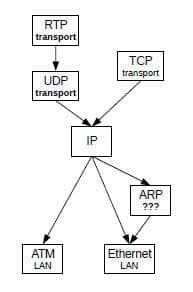
Trying to fit protocols into specific layers is often both futile and irrelevant. From one perspective, the RealTimeProtocol RTP lives at the Transport layer, but just above the UDP layer; others have put RTP into the Application layer. Parts of the RTP protocol resemble the Session and Presentation layers. A key component of the IP protocol is the set of various router-update protocols; some of these freely use higher-level layers.
Similarly, tunneling might be considered to be a Link-layer protocol, but tunnels are often created and maintained at the Application layer.
Understanding Layers
A sometimes-more-successful approach to understanding «layers» is to view them instead as parts of a protocol graph. Thus, in the following diagram we have two protocol sublayers within the transport layer (UDP and RTP), and one protocol (ARP) not easily assigned to a layer.
References:
- ITU-T Telecommunication Standardization Sector X.200 – Open Systems Interconnection – Model and Notation.
- Computer Networking: Principles, Protocols and Practice, Olivier Bonaventure.(learn more)
- An Introduction to Computer Networks, Peter L Dordal
- High Performance TCP/IP Networking – Concepts, Issues and Solutions, Mahbud Hassan and Raj Jain (learn more)