Definition of Internet Group Management Protocol (IGMP) in Network Encyclopedia.
What is IGMP (Internet Group Management Protocol)?
IGMP stands for Internet Group Management Protocol, is a TCP/IP network layer protocol used for informing routers of the availability of multicast groups on the network.
How it works
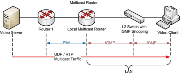
In a multicasting environment, Internet Group Management Protocol (IGMP) is used to exchange information on the status of membership in multicast groups between routers on the network. In other words, once a router becomes aware that there are hosts on a locally attached network that are members of a particular multicast group, it advertises this information to other routers on the internetwork so that multicast messages are forwarded to the appropriate routers.
To join a multicast group, a host must report its request for membership to nearby routers. These routers periodically poll the hosts in their locally attached networks to check on their membership status. When a host first joins a multicast group, it sends an IGMP message called a Host Membership Report that is directed to the multicast address 244.0.0.1 containing the multicast address that identifies the group it wants to join. Routers connected to that host’s local network then advertise to other routers throughout the internetwork that the particular network has hosts belonging to that multicast group.
The routers poll the hosts regularly by sending Host Membership Query messages to determine whether any of them are still members of that group. If no hosts on the network belong to that group any longer, the router stops advertising the information to other routers on the internetwork so that multicast messages directed to that group are no longer forwarded to it.
IGMP messages
IGMP messages are encapsulated in IP datagrams. To indicate an IGMP packet, the IP header contains a protocol number of 2. For IGMP version 2 (defined by RFC 2236), the IP data field contains the 8-octet IGMP message shown in Figure 6-2.
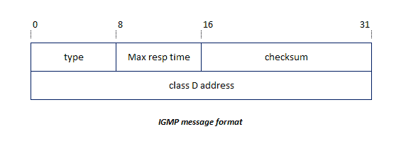
The fields in the IGMP message contain the following information:
Type: This field specifies the type of IGMP packet:
- 0x’11’: Specifies a membership query packet. This is sent by a multicast router. There are two subtypes of membership query messages:
- General Query: This is used to learn which groups have members on an attached network.
- Group-Specific Query: This is used to learn if a particular group has any members on an attached network.
- 0x’12’: Specifies an IGMPv1 membership report packet. This is sent by a multicast host to signal participation in a specific multicast host group.
- 0x’16’: Specifies an IGMPv2 membership report packet.
- 0x’17’: Specifies a leave group packet. This is sent by a multicast host.
Max resp time: This field is used in membership query messages. It specifies the maximum allowed time a host can wait before sending a corresponding report. Varying this setting allows routers to tune the leave latency. This references the time between the last host leaving a group and the time the routing protocol is notified that there are no more members.
Checksum: This field contains a 16-bit checksum.
Class D Address: This field contains a valid multicast group address. It is used in a report packet.
IGMPv3 messages
The IGMPv2 message format has been extended in IGMP version 3, defined in RFC 3376 (which obsoletes RFC 2236). Version 3 allows receivers to subscribe to or exclude a specific set of sources within a multicast group. To accommodate this, The 0x’11’ type membership query packet has been altered, and a new IGMP packet type of 0x’22’ has been added. However, all IGMPv3 implementations must still support packet types 0x’12’, 0x’16’, and 0x’17’.
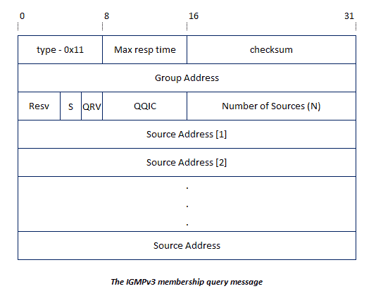
The fields from this message are as follows:
Type: This remains unchanged and, in the case of the membership query message, has a value of 0x’11’.
Max resp code: This field is has been changed from the IGMPv2 convention, and distinguishes between a maximum response code and a maximum response time. The time can be determined from the code as follows:
If the maximum response code is less than 128, the value of maximum response code is also the maximum response time.
If the maximum response code is greater than 128, the maximum response code represents a floating-point value denoted as follows:
- Byte 0 = 1
- Bytes 1-3 = exp
- Bytes 4-7 = mant
Maximum response time = (mant OR 0x’10) << (exp + 3)
Note: Maximum response time, for both IGMPv2 and IGMPv3, is measured in tenths of second.
This can be better described as creating a 5-bit string starting with 1 followed by the 4 bits of mant, and then shifting this string exp+3 to the left. The resulting value is the maximum response time. For example, assume that the value of maximum response code is decimal 178. The bit string representation of this is 10110010. From this, the fields of the maximum response code are:
- Byte 0 = 1
- exp = 011
- mant = 0010
The subsequent calculations are (note that the exp calculation uses a
binary representation of decimal 3):
- (mant OR 0x10) = (0010 OR 10000) = 10010
- 10010 << exp + 11 = 10010 << 110 = 10010000000
- Binary 10010000000 = Decimal 1152
Therefore, when the maximum response code is decimal 178, the
maximum response time is 1152 tenths of a second.
Checksum: This field contains a 16-bit checksum, and remains unchanged
from its version 2 counterpart.
Group Address: This field contains the Class D address, and remains
unchanged from its version 2 counterpart.
Resv: This field is reserved, and is set to zero on transmission and ignored on reception.
S Flag: When set to 1, this field indicates that any receiving multicast routers should suppress the normal timer updates normally performed upon hearing a query.
QRV: This field is the Querier’s Robustness Variable. The QRV was added in IGMPv3, and is used in tuning timer values for expected packet loss. The higher the value of the QRV, the more tolerant the environment is for lost packets within a domain. However, increasing the QRV also increases the latency required in detecting a problem. Routers adopt the value in this field from the most recently received query as their own robustness variable. If this value exceeds the limit of 7, it is reset to 0.
QQIC: This field is the Querier’s Query Interval Code. This value, specified in seconds, specifies the query interval used by the originator of this query. The calculations to convert this code into the actual interval time is the same used for the maximum response code.
Number of Sources (N): This field indicates how many source address are contained within the message. The maximum value for this field is determined by the MTU allowed in the network.
Source Addresses: This set of fields are a vector of N IP unicast addresses, where the value N corresponds to the Number or Sources (N) field.
Additionally, IGMPv3 adds a new type of 0x’22’, which is the IGMPv3 Membership Report. The next figure illustrates the format for this message.
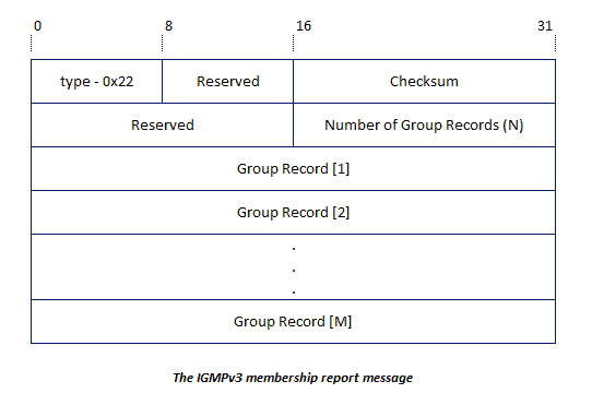
In the figure above, the Type, Checksum, and Number of Group Records fields are equivalent to their IGMPv3 message query counterparts. However, in the membership report message, each Group Record is broken up, as illustrated in the next figure.
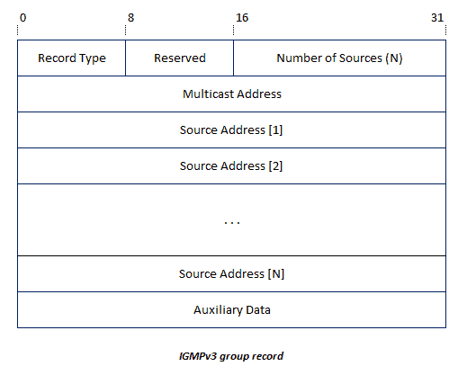
The fields within the group record are described as follows:
Record Type: This field indicates whether the group record type is a current-state, filter-mode-change, or source-list-change record. The values are as follows:
Current-state records are sent by a system in response to a query
received on an interface, and report the current reception of that interface.
There are two group record values that denote a current-state record:
- MODE_IS_INCLUDE: This indicates that the interface has a filter mode
of INCLUDE for the specified multicast addresses. - MODE_IS_EXCLUDE: This indicates that the interface has a filter-mode of EXCLUDE for the specified multicast addresses.
Filter-mode-change records are sent by a system whenever an interface’s
state changes for a particular multicast address. There are two group
record values which denote a filter-mode-change record:
- CHANGE_TO_INCLUDE_MODE: This indicates that the interface has
changed to the INCLUDE filter-mode for the specified multicast
addresses. - CHANGE_TO_EXCLUDE_MODE: This indicates that the interface has
changed to the EXCLUDE filter-mode for the specified multicast
addresses.
Source-list-change records are sent by a system whenever an interface
wants to alter the list of source addresses without altering its state. There
are two group record values that denote a source-list-change record:
- ALLOW_NEW_SOURCES: This indicates that the interface has changed such that it wants to receive messages from additional sources. If the filter is an INCLUDE filter, the specified multicast addresses will be added. If it is an EXCLUDE filter, the specified multicast addresses will be removed.
- BLOCK_OLD_SOURCES: This indicates that the interface has changed such that it no longer wants to receive messages from additional sources. If the filter is an INCLUDE filter, the specified multicast addresses will be removed. If it is an EXCLUDE filter, the specified multicast addresses will be added.
Source-list-change records are sent by a system whenever an interface wants to alter the list of source addresses without altering its state. There are two group record values that denote a source-list-change record:
- ALLOW_NEW_SOURCES: This indicates that the interface has changed such that it wants to receive messages from additional sources. If the filter is an INCLUDE filter, the specified multicast addresses will be added. If it is an EXCLUDE filter, the specified multicast addresses will be removed.
- BLOCK_OLD_SOURCES: This indicates that the interface has changed such that it no longer wants to receive messages from additional sources. If the filter is an INCLUDE filter, the specified multicast addresses will be removed. If it is an EXCLUDE filter, the specified multicast addresses will be added.
IGMP operation
Both hosts and multicast routers participate in IGMP functions.
Host operations
To receive multicast datagrams, a host must join a host group. When a host is multihomed, it can join groups on one or more of its attached interfaces. If a host joins the same group on multiple interfaces, the multicast messages received by the host can be different. For example, 244.0.0.1 is the group for all hosts on this subnet. Messages in this group received through one subnet will always be different from those on another subnet.
Multiple processes on a single host can listen for messages from the same group. When this occurs, the host joins the group once. The host internally tracks each process interested in the group.
To join a group, the host sends an IGMP membership report packet through an attached interface. The report is addressed to the desired multicast group. A host does not need to join the all hosts group (224.0.0.1). Membership in this group is automatic.
IGMPv3 specific host operations
In IGMPv3, hosts specify a list of multicast addresses from which they want to receive messages or a list of multicast addresses from which they do not want to receive messages. Hosts can then later alter these lists to add or remove multicast addresses. This can be achieved using the filter-mode-change and source-list-change records.
Note: If no interface state exists, it is created using the filter-mode-change record.
The use of these records is demonstrated using Table 6-1. In this example, the current state indicates what subsets of multicast addresses (A and B) are currently included or excluded. The desired state indicates the subsets desired to be included or excluded. The Records needed to achieve desired state show the records which can be sent to achieve this change. Note that the group type records are abbreviated as follows:
- CHANGE_TO_INCLUDE_MODE: To_in
- CHANGE_TO_EXCLUDE_MODE: To_ex
- ALLOW_NEW_SOURCES: Allow
- BLOCK_OLD_SOURCES: Block
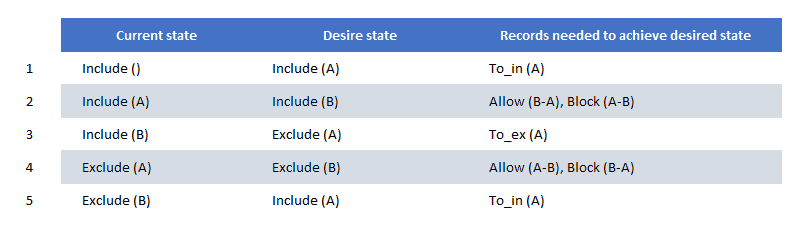
These steps are summarized as follows:
- No source address lists currently exist. The subset of lists A is added by issuing a CHANGE_TO_INCLUDE_MODE specifying the A subset.
- Subset A is currently included. However, only subset B is desired. To do this, first, an ALLOW_NEW_SOURCES message is issued to add all of subset B except for those addresses already included in A. This is followed by a BLOCK_OLD_SOURCES message to exclude all of subset A except for those addresses which also belong to B.
- Now only subset B is included. However, we want to change the filter to EXCLUDE, and to specify only subset A. This is done with one CHANGE_TO_EXCLUDE_MODE specifying subset A.
- After step 3, only subset A is excluded. Now, we want to exclude only subset B. First issue an ALLOW_NEW_SOURCES message to remove all of subset A from the excluded list except those addresses also in subset B. Then add all of the addresses in subset B to the exclude list except for chose also in subset A.
- Now only subset B is excluded. We want to change the filter to INCLUDE and add A to the list. Use the CHANGE_TO_INCLUDE_MODE specifying
subset A.
Multicast router operation
When a host attempts to join a group, multicast routers on the subnet receive the membership report packet and create an entry in their local group database. This database tracks the group membership of the router’s directly attached networks.
Each entry in the database is of the format [group, attached network]. This indicates that the attached network has at least one IP host belonging to the group. Multicast routers listen to all multicast addresses to detect these reports.
The information in the local group database is used to forward multicast datagrams. When the router receives a datagram, it is forwarded out each interface containing hosts belonging to the group.
To verify group membership, multicast routers regularly send an IGMP query message to the all hosts’ multicast address. Each host that still wants to be a member of a group sends a reply. RFC 3376 specifies this verification should by default occur every 125 seconds. To avoid bursts of traffic on the subnet, replies to query messages are sent using a random delay. Because routers do not track the number of hosts in each group, any host that hears another device claim membership cancels any pending membership replies. If no hosts claim membership within the specified interval, the multicast router assumes no hosts on that network are members of the group.
IGMP snooping switches
One potential problem when implementing IGMP is the flooding of a network segment with multicast packets, even though there might not be any nodes on that segment that have any interest in receiving the packets. Although the amount of processing involved in receiving these packets presents no significant cost, the flooding of these packets does have the potential to waste bandwidth.
This problem is documented in RFC 4541, which provides recommendations and suggested rules to allow network switches to “snoop” on IGMP traffic. By doing so, switches can analyze the data contained within the IGMP header and determine if the traffic needs to be forwarded to every segment to which the switch is connected. By doing this, switches can reduce the amount of unnecessary IGMP traffic flooding uninterested networks, thereby reserving the segment’s bandwidth for the traffic with which the hosts on those networks are concerned.