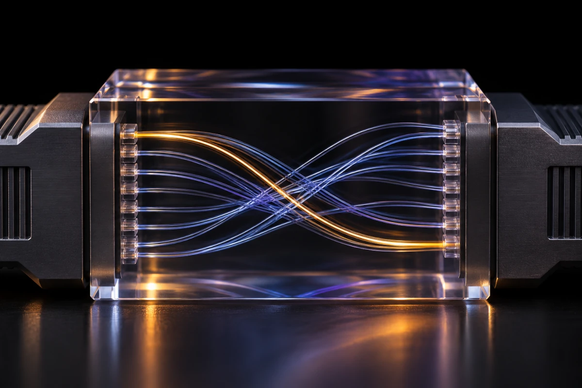
The new cable clicks into both switches. The optics are compatible. Every strand can carry light from one end to the other. The link still won’t come up.
Now follow the first strand. At one switch, it starts at a transmitter. At the other, it ends at another transmitter. The light arrived. It just went to a place that wasn’t listening.
That is the problem MPO fiber polarity solves. In a multifiber link, a connector can fit and all the fibers can have continuity while the channel still sends the signals to the wrong positions.
What Is MPO Fiber Polarity?
An MPO (multi-fiber push-on) connector brings several fibers together in one ferrule, the part that holds them in alignment. The connector’s key controls how it mates. A position-1 mark helps identify the numbering reference. And the fibers inside the assembly determine which numbered position at one end reaches which position at the other. [1]
Polarity is about making that mapping work for the application. Every transmit lane must reach its intended receive lane at the far end, and the same must be true in the reverse direction. Number the positions using the documented connector view. Looking at the opposite face without adjusting the reference can turn the map into its mirror image.
You’ll also see the name MTP®. That’s a US Conec brand of MPO connectors. The brand name alone does not tell you the fiber count, position map, pin configuration, or polish of the assembly. [2]
Our fiber-optic cabling overview explains how a transmitter and receiver communicate over fiber. MPO polarity takes that same idea and asks you to track several paths at once.
Three Cable Maps That Can Look Alike from the Outside
For a single-row, 12-position MPO assembly, three familiar cable types map positions as follows. These are cable maps: the position numbers describe the two connector ends, not a universal assignment of transmitters and receivers. [1]
| Cable type | What it does | Examples from end 1 to end 2 |
|---|---|---|
| Type A | Preserves the order. | 1 → 1, 2 → 2, …, 12 → 12 |
| Type B | Reverses the full row. | 1 → 12, 2 → 11, 3 → 10, …, 12 → 1 |
| Type C | Swaps the two positions within each adjacent pair. | 1 → 2, 2 → 1, 3 → 4, 4 → 3, …, 12 → 11 |
Type C’s pair swaps can serve duplex applications in an appropriately designed channel. In the SR4 example below, positions 1 and 2 are both transmit positions. Swapping them still leaves a transmitter connected to a transmitter. A pair swap and a full reversal solve different problems.
One useful distinction when ordering parts: a cable type describes an assembly; a polarity method describes how components are combined in a channel. The same letter can appear in cable, adapter, and method descriptions. Find out which component the label identifies. Standards-based approaches go beyond the three maps in the table: ANSI/TIA-568.3-E introduced U1 and U2 connectivity methods for MPO-based duplex applications. That is another reason to check the documented channel design rather than build from letters alone. [1, 3, 4]
A Worked Example: Two 40GBASE-SR4 Optics
Take two compatible 40GBASE-SR4 modules with the MPO-12 layout documented by Cisco. Four positions transmit, four receive, and the middle four are unused in this application. Here’s where the transmit lanes at end A need to go: [5]
| Transmit lane at end A | Position at end A | Matching receive position at end B |
|---|---|---|
| Lane 1 | 1 | 12 |
| Lane 2 | 2 | 11 |
| Lane 3 | 3 | 10 |
| Lane 4 | 4 | 9 |
A straight-through path sends position 1 to position 1. It joins the two transmit positions and leaves their corresponding receivers connected to each other. The glass can be intact at every position and the link can still be dark at the receivers.
For these two optics with one direct cable, a Type B map supplies the required full reversal: 1 goes to 12, 2 to 11, and so on. The map is reciprocal, so it also takes transmit position 1 at end B to receive position 12 at end A. The cable still has to meet the modules’ requirements for fiber, connector, pins, polish, and optical loss. This example does not tell you what to order for a different optic, a breakout, or an installed trunk. [1, 5, 6]
A Good Cable Can Create a Bad Channel
Suppose you replace that direct cable with a structured channel: at each end there’s a patch cord and a panel, and between the panels there’s a trunk. Now the useful question is what happens to position 1 from transceiver to transceiver, not what one label says.
In a consistent end-to-end numbering reference, two full reversals cancel: 1 → 12 → 1. Likewise, two straight-through segments remain straight through. Those are statements about verified position maps. They are not a recipe for predicting the full channel from the letter printed on each part. Adapters determine which connector faces mate, and cassettes or breakouts can add their own internal mapping. Establish the numbering reference at each mating point before following the route.
This is an optical cousin of the split pair Ethernet cable. The faults are different: a split pair breaks the electrical pair relationship, while wrong MPO polarity connects the wrong optical endpoints. Both can hide behind a test that answers a narrower question than the one you need answered.
The same discipline applies to a larger optical fabric. An optical circuit switch can change the fiber path, but it cannot make a signal received at the wrong endpoint count as a correct connection.
Pins, Polish, and Dirt Can All Masquerade as a Polarity Fault
The key, alignment pins, and position map have separate jobs. The key orients the connection. The pins align the ferrules. The position map determines where each strand ends. At a conventional physical-contact MPO mating point, a pinned connector mates to an unpinned connector. Two sets of pins can collide; two unpinned ferrules lack the intended pin alignment. Check the actual module and cabling documentation before mating anything. [1, 2, 6]
Also check the end-face polish and fiber specification. An angled physical contact (APC) interface requires compatible mating geometry. An MPO-shaped shell is no assurance that you have the right combination of polish, fiber type, and array layout. A correctly mapped channel can still fail if a dirty end face or excessive insertion loss leaves too little usable optical power. [4, 6, 7]
From “Link Down” to a Useful Test
- Identify both optics and the intended mode. Record the exact part numbers and supported settings. Get the manufacturer’s lane map and check speed, breakout mode, and FEC where applicable. Two modules that share a connector shape need not be interoperable.
- Trace the installed channel. Write down the patch cords, adapters, trunk, and any cassettes or breakouts. For each required transmit position, predict the far-end receive position. Verify both directions and compare the prediction with the intended design.
- Inspect and clean before reconnecting. Follow site procedures to isolate optical sources and use an appropriate fiber inspection probe. Never look into a fiber or transceiver port to check for light. Inspect the relevant mating surfaces, clean as needed, and inspect again. [6, 7]
- Measure routing and loss separately. Use a multifiber test setup that matches the connection under test. Compare its measured position map with the design, then measure insertion loss on the relevant fibers against the link’s budget. A continuity check can tell you a strand is intact; it cannot certify the intended mapping or the loss budget by itself. [7]
- Isolate and verify. If a service window and physical layout allow, test the same optics with a known-good, correctly specified direct assembly. A working direct link points you back toward the installed channel or its component compatibility; it doesn’t prove polarity by itself. After the fix, verify link operation and record the tested map so the next patch-cord change doesn’t bring the fault back.
When a link stays down after a cable change, resist the urge to start by swapping optics. Pick one transmit lane. What numbered position does it reach at the far end, and what is actually listening there?
References and Further Reading
- Fluke Networks: 12-Fiber MPO Polarity — position mapping, key orientation, and the distinction between assemblies and connectivity methods.
- US Conec: MTP PRO Connector Polarity Guidelines — MPO connector family and manufacturer guidance.
- TIA: ANSI/TIA-568.3-E Optical Fiber Cabling Component Standard announcement — scope and publication of the revision.
- Siemon: ANSI/TIA-568.3-E Introduces New Polarity Methods — U1 and U2 duplex connectivity methods and mating considerations.
- Cisco: What Are Breakouts and How Do You Use Them? — Figure 7 documents the illustrated MPO-12 lane arrangement.
- Cisco: 40-Gigabit QSFP+ Transceiver Modules Installation Note — supported connectors, connection procedure, and laser safety.
- Fluke Networks: MPO Connectors in Data Centers — multifiber inspection and testing for insertion loss and polarity.