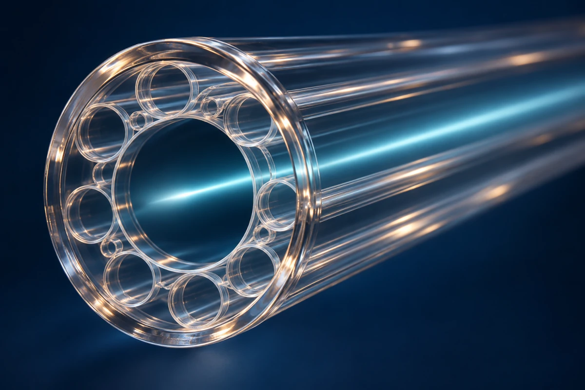
An optical fiber can be made from glass while deliberately keeping most of its light out of the glass.
That is the intriguing idea behind hollow-core fiber: use a carefully structured glass surround to guide light primarily through an empty central region, usually filled with air or another gas. The glass remains essential. It just stops being the main material through which the signal travels. [1]
For networking, the appeal starts with a basic physical fact: light propagates more slowly through conventional glass-core fiber than through air. Change the medium carrying most of the light, and you can reduce the time a signal spends in transit.
The interesting questions are how to keep the light inside that hollow channel, how much time this actually saves, and whether the result survives contact with a real cable route.
What Is Hollow-Core Fiber?
Conventional communications fiber guides light in a solid glass core surrounded by cladding. A hollow-core design instead places a low-index hollow region at the center and uses a structured cladding to confine the optical field.
Researchers distinguish two major families: photonic band-gap hollow-core fibers and antiresonant hollow-core fibers. They use different wave-guiding structures; “hollow core” does not name one universal internal geometry. [1]
Our fiber-optic cabling overview introduces the familiar medium. Here, the novelty is where the light is guided inside it.
How Can a Hole Keep Light Inside?
This is the first useful puzzle. Ordinary glass-core guidance cannot simply be turned inside out and explained with the same total-internal-reflection picture.
In an antiresonant design, thin glass membranes and capillary structures around the central region are engineered to suppress light escaping at the intended wavelengths. Their dimensions make the surrounding structure a wavelength-dependent barrier to leakage. This is a wave-guiding effect, rather than an empty hose lined with an ordinary mirror. [1][9]
Think of a corridor whose walls are designed around the behavior of waves. The corridor is mostly empty, but removing the walls would remove the guide.
The 2025 low-loss research discussed below uses double-nested antiresonant nodeless fiber, or DNANF: an elaborate glass microstructure around the air core. The impressive engineering is making that delicate structure accurately and consistently over long lengths. [9]
The 100-Kilometer Thought Experiment
For pulse travel time, the useful quantity is the mode’s group index. A simple propagation calculation is:
Propagation time = fiber length × group index / speed of light in vacuumTake a 100-kilometer fiber length. For the conventional fiber, use a representative group index rounded to 1.468. Corning’s SMF-28 Ultra data sheet, for example, specifies 1.4682 at 1,550 nm. For the hollow-core comparison, approximate the group index as 1.000. That is a simplified near-air model, not a specification for every HCF product. [2]
Using the vacuum speed of light, 299,792,458 meters per second, gives the following calculated values. [3]
| Quantity for the same 100 km of fiber | Conventional glass-core model | Near-air hollow-core model |
|---|---|---|
| Assumed group index | 1.468 | 1.000 |
| One-way propagation time | About 490 microseconds | About 334 microseconds |
| Difference | — | About 156 microseconds less |
These are model calculations, not measurements of an installed link. Real group delay depends on fiber design and wavelength; a hollow-core mode still interacts with its surrounding structure.
The comparison produces two different percentages:
- Propagation speed increases by about 47%. The near-air model travels about 1.468 times as fast.
- Propagation time decreases by about 32%. The journey takes about 1 / 1.468 as long.
“47% faster” and “47% less delay” are therefore different claims. In this example, only the first describes the speed comparison.
Why Your Ping Would Not Necessarily Fall by 32%
Propagation is one component of network latency. A complete exchange can also include serialization, equipment processing, queues, and the destination’s response time.
If both directions each traverse a replaced 100-kilometer span, the model saves about 312 microseconds, or 0.312 milliseconds, across the round trip. That assumes the same fiber lengths and no changes elsewhere.
For an invented connection with a total RTT of 50 milliseconds, that isolated saving would bring the result to roughly 49.688 milliseconds—about a 0.6% reduction in the total. It would not reduce the complete RTT by 32%.
This does not make the saving unimportant. It identifies where it matters. On a carefully engineered low-latency link, a few hundred microseconds may be valuable. On a connection dominated by queues or a slow application, the same physical improvement changes a smaller part of the experience.
RFC 2681 also reminds us that a round-trip measurement combines two paths, which can differ in routing and queueing. A ping is not a direct measurement of one fiber’s propagation delay. [4]
Our bandwidth-delay product guide explains another consequence: capacity and round-trip delay interact in transport performance, while remaining different quantities.
Faster Propagation Is Not Automatically More Bits per Second
A signal can arrive earlier while the link continues transmitting at the same bit rate. If the transceivers still operate at the same rate, the time required to serialize a packet has not changed merely because the pulse travels through a different core.
Three properties need separate questions:
| Property | The question it answers |
|---|---|
| Propagation delay | How long does the signal take to travel through the link? |
| Attenuation | How much optical power is lost along the fiber? |
| Transmission capacity | How much information can the complete optical system carry per second? |
Hollow-core designs can offer benefits beyond propagation. Keeping more optical power out of glass reduces interaction with that material, opening opportunities involving loss, nonlinear effects, and usable optical bandwidth. The final system still depends on the fiber, wavelengths, transceivers, amplification, and operating conditions. [5][9]
Likewise, single-mode fiber describes modal behavior, not a rule allowing only one data signal or wavelength channel. Core structure, modal behavior, propagation delay, and system capacity are related design questions, not interchangeable labels.
The Loss Breakthrough That Made People Pay Attention
Moving the light into air is attractive only if enough of it reaches the other end.
In a paper published in Nature Photonics on September 1, 2025, researchers reported a hollow-core fiber with measured attenuation of 0.091 dB per kilometer at 1,550 nm. Their longer test fiber was 15 kilometers, allowing more accurate low-loss characterization than their shorter initial sample. [5]
That is a fiber attenuation result under the study’s conditions. It is not the total loss of an arbitrary installed link, which also has terminations, splices, bends, and connections to other components.
The result matters because it challenges the assumption that faster air guidance must inevitably carry a large loss penalty. It does not mean every hollow-core cable on every route now meets that research value.
The paper received an author correction in October 2025 concerning a figure’s wavelength-axis labeling; the corrected publication remains the appropriate reference. [5]
From a Drawing Tower to a Working Route
The air channel does not make manufacturing simple.
Southampton’s fabrication group describes drawing a large glass preform into kilometers of microscopic fiber while controlling temperature, pulling speed, and gas pressure within the structure. Protective polymer coating is then applied. The internal geometry must survive that process with the optical properties intact. [7]
Installation introduces another set of requirements: cable manufacture, field splicing, interfaces to conventional fiber, testing, and route protection.
There is evidence beyond laboratory reels. In a March 20, 2025 deployment report, Microsoft’s Azure Networking team described two metropolitan data-center routes, each more than 20 kilometers long. The hybrid cables contained both hollow-core and conventional single-mode strands, and the report described HCF carrying live customer traffic. [6]
That is an important category of evidence: an operator reporting an installed, operational system. It is also a bounded observation, rather than proof that every deployment will have identical economics or reliability.
The glass microstructure may be the scientific breakthrough. Turning it into a service requires the rest of the network to work with it.
Read the Fine Print on Spectacular Distance Records
A long transmission experiment and a long newly installed cable route are different achievements.
For example, a Microsoft Research listing for ECOC 2025 reports HCF transmission experiments reaching 11,154 kilometers using a roughly 360-kilometer recirculating loop. The signal repeatedly traversed the experimental loop; the result does not describe an 11,154-kilometer physical cable installation. [8]
Such experiments are valuable for studying accumulated transmission effects. Field deployments answer additional questions about manufacturing scale, installation, maintenance, and operation over time.
When reading a headline, ask what was measured: a fiber’s attenuation, a transmission system’s experimental reach, or a working network route. Those results complement one another, but one cannot silently stand in for all three.
Where Air Can Make the Biggest Difference
The strongest case starts with a workload and a route, rather than a percentage in isolation.
For latency-sensitive data-center interconnects, the benefit may be earlier responses. Another option is more distance within the same propagation-delay budget: a faster medium can let sites be farther apart before consuming that budget. The complete design must still account for route length, optical reach, equipment, and service requirements.
For a congested access link, fixing queues may matter more immediately. For an optical system constrained by power loss or nonlinear effects, the important benefit may involve more than arrival time.
Hollow-core fiber is compelling because it changes a physical part of the network’s delay budget. It does so with glass still performing a sophisticated job: constructing a path in which the most useful material is the space left inside.
References and Further Reading
- University of Southampton ORC: Hollow Core Fibre Group—guidance mechanisms and microstructured cladding.
- Corning: SMF-28 Ultra Optical Fiber Product Information, July 2025—effective group index at 1,550 nm.
- NIST: Speed of Light in Vacuum.
- RFC 2681: A Round-Trip Delay Metric for IPPM—path asymmetry and measurement interpretation.
- Petrovich et al., Broadband Optical Fibre With an Attenuation Lower Than 0.1 Decibel per Kilometre, Nature Photonics, 2025; author correction, October 17, 2025.
- Microsoft Azure Networking: The Deployment of Hollow Core Fiber in Azure’s Network, March 20, 2025.
- University of Southampton: Hollow Core Fibre Fabrication.
- Hong et al., Real-Time, Fully-Loaded C-band, Low-Latency, Long-Haul Transmission Over Hollow-Core Fiber, ECOC 2025—recirculating-loop experiment.
- University of Southampton: Record-Low Signal Loss With Hollow Core Fibre, September 23, 2025—DNANF structure and research context.