In the world of modern systems design, the Unified Modeling Language (UML) serves as the “blueprints” for the digital age. Created in the 1990s to unify a fragmented industry, UML provides a standardized visual language that helps architects, developers, and network engineers communicate complex system behaviors without writing a single line of code.
However, as we move away from traditional “castle-and-moat” security toward Zero Trust Architectures (ZTA), the need for precise documentation has never been higher. This article will briefly review the foundations of UML before diving deep into how you can use it to model the dynamic, identity-centric logic required by a Zero Trust framework.
In this article:
- UML Fundamentals – The Industry Standard
- The Zero Trust Challenge – Why Visualization Matters
- Mapping Zero Trust Principles to UML Diagrams
- Case Study – Modeling a Secure API Request
- Tools and Best Practices for Security Architects
- Conclusion
1. UML Fundamentals – The Industry Standard
Before we dive into the high-stakes world of modern security, we have to talk about the “Method Wars” of the 1990s. Back then, if you asked three different software architects to map out a system, you’d get three different sets of symbols, icons, and logic. It was a chaotic era of “Franken-diagrams” that made cross-team collaboration a nightmare.
The “Three Amigos” and the Birth of a Legend
The chaos ended when three rivals at Rational Software—Grady Booch, James Rumbaugh, and Ivar Jacobson—decided to stop competing and start collaborating. Known affectionately in the industry as the “Three Amigos,” they combined their respective methodologies (the Booch method, OMT, and OOSE) into a single, powerhouse language.
The result was the Unified Modeling Language (UML). It wasn’t just a new way to draw; it was a universal “lingua franca” for anyone building complex systems. By 1997, it became the international standard, ensuring that a diagram drawn in London would be perfectly understood by an engineer in Tokyo.
Structural vs. Behavioral: The Two Sides of the Security Coin
UML is organized into two distinct categories, and for those interested in Modeling Zero Trust Architecture with UML, understanding the difference is non-negotiable:
- Structural Diagrams: These represent the “nouns” of your system. They define the static parts—the servers, the databases, the users, and the components. In a Zero Trust context, this is where you define your Micro-perimeters and Identity Providers.
- Behavioral Diagrams: These represent the “verbs.” They show how the system moves, reacts, and flows over time. For security, this is where the magic happens—modeling the precise steps of an authentication handshake or a policy check.
The Goal: Beyond “Boxes and Arrows”
We’ve all seen them: those informal whiteboard sketches where a cloud icon is connected to a box labeled “Security” with a single, vague arrow. That might work for a quick brainstorm, but it’s a liability for mission-critical infrastructure.
The goal of UML is to move us toward rigorous, standardized documentation. When you use UML, you aren’t just “drawing”; you are creating a blueprint that is:
- Ambiguity-Free: There is no guessing what a solid line vs. a dashed line means.
- Scalable: You can drill down from a high-level overview to the granular logic of a single API call.
- Auditable: In a Zero Trust environment, having a standardized model makes it significantly easier to prove compliance to auditors and stakeholders.
2. The Zero Trust Challenge – Why Visualization Matters
In the “old days” of networking, security was simple: you built a giant wall around your data center. If you were inside the wall, you were trusted; if you were outside, you weren’t. We called it the “castle-and-moat” strategy, and our network diagrams reflected that—usually with a big, friendly cloud for the Internet and a series of nested boxes for our internal zones.
But those days are over.
The Death of the Perimeter
Traditional network diagrams are excellent at showing where a cable goes or which VLAN a server sits on, but they are notoriously bad at explaining why a connection is allowed. In a Zero Trust world, the “perimeter” has dissolved. It has moved from the edge of the network to every individual user, device, and workload.
If you try to map a Zero Trust environment using old-school topology icons, you’ll quickly find yourself in a mess of overlapping lines. Traditional diagrams focus on location, but Zero Trust focuses on identity and context. This shift is exactly why Modeling Zero Trust Architecture with UML has become a vital skill; it allows us to document the logic of the connection rather than just the physical path.
Complexity Overload: The PDP and PEP Puzzle
The heart of Zero Trust lies in the relationship between two critical components:
- The Policy Decision Point (PDP): The “brain” that decides if access is granted based on signal intelligence (user health, location, time, etc.).
- The Policy Enforcement Point (PEP): The “brawn” that actually blocks or allows the traffic (like a gateway or an agent).
Managing the communication between these two—especially when thousands of requests happen per second—creates a massive amount of cognitive load for architects. A simple text document can’t capture the “if-this-then-that” nuances of a PDP’s logic. Without a standardized visual model, you risk leaving security gaps where the brain and the brawn fall out of sync.
The Abstraction Layer: Bridging the Gap
One of the hardest parts of a security architect’s job isn’t the technology—it’s the people. You have to explain complex security requirements to stakeholders who might not know a packet from a pocket.
UML acts as an abstraction layer. It allows you to present a high-level view of the security flow to a CISO (Chief Information Security Officer) using a Use Case diagram, while simultaneously providing a granular Sequence Diagram for the developers who have to write the authentication code. By using a standardized language, you ensure that everyone—from the boardroom to the server room—is looking at the same map.
3. Mapping Zero Trust Principles to UML Diagrams
Now that we understand the “why,” it’s time to look at the “how.” When you are Modeling Zero Trust Architecture with UML, you aren’t just using one type of diagram. You are choosing the specific tool that best illustrates a particular security principle.
Here is how the three heavy hitters of the UML world map directly to Zero Trust requirements.
Sequence Diagrams for Authentication: The “Always Verify” Handshake
In a Zero Trust environment, the mantra is “Never Trust, Always Verify.” A Sequence Diagram is the perfect way to model this because it focuses on the timing and order of messages between different objects.
Instead of just saying “the user logs in,” a Sequence Diagram allows you to visualize the rigorous handshake:
- The User requests access.
- The Resource redirects the request to the Identity Provider (IdP).
- The IdP challenges the user for MFA and checks device health.
- Only after verification is a temporary token issued.
By modeling this sequence, you can identify “logic gaps” where a session might be hijacked or where a verification step is missing.
Activity Diagrams for Policy Logic: The Brain of the Policy Engine
If the Sequence Diagram is about the handshake, the Activity Diagram is about the decision. This is where you model the internal logic of your Policy Decision Point (PDP).
Think of an Activity Diagram as a sophisticated flowchart. It allows you to map out the “if-then-else” logic that governs access:
- Decision Diamond: Is the user connecting from a known IP?
- Parallel Processing: Simultaneously check the user’s department in AD and the current threat level of the network.
- Merge Points: If all conditions are met, proceed to grant access; otherwise, trigger a “Deny” or “Step-up Authentication” action.
Visualizing this logic ensures that your security policies are consistent and that no “edge case” allows an unauthorized user to slip through.
Component Diagrams for Micro-segmentation: Visualizing Isolation
In a cloud-native, microservices-heavy world, you can’t treat your network as one big bucket. You need Micro-segmentation.
Component Diagrams are the gold standard for this. They allow you to show how a system is divided into smaller, autonomous pieces and, crucially, how those pieces are allowed to talk to each other.
- Interfaces: Clearly define which APIs are exposed to other services.
- Dependencies: Show exactly which service “requires” another, allowing you to implement a Least Privilege model.
- Boundaries: Use UML packages or boundaries to visually represent the secure “bubbles” around specific workloads.
Using these diagrams makes it clear to both the network and DevOps teams exactly where the firewalls and identity checks need to be placed to maintain a Zero Trust posture.
4. Case Study – Modeling a Secure API Request
Theory is fine, but in the fast-paced world of network engineering, we need to see how these diagrams actually function in the wild. Let’s look at a practical application of Modeling Zero Trust Architecture with UML by examining a common high-security scenario.
The Scenario: The Remote Auditor
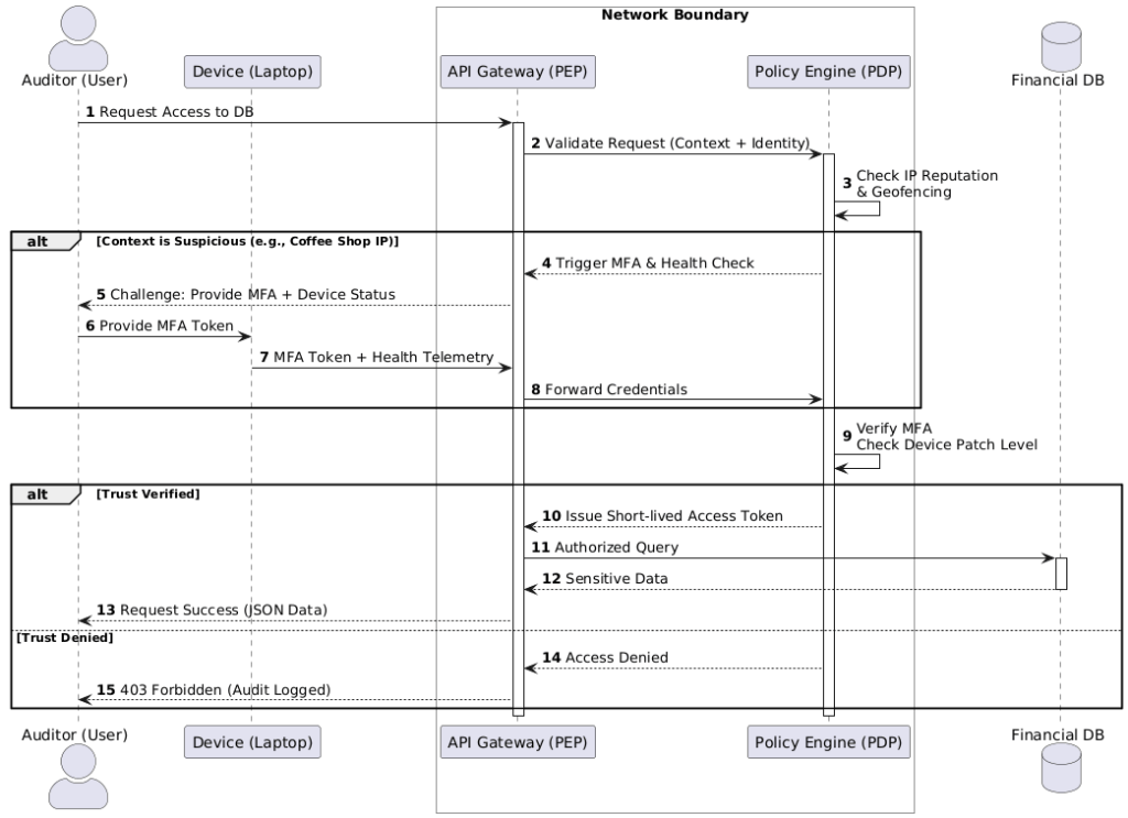
Imagine a remote auditor working from a coffee shop. They need to access a Sensitive Financial Database hosted in your private cloud. In a legacy network, if they were on the VPN, they were “in.” In our Zero Trust model, the VPN is irrelevant; we need to verify every single request to that database.
Step-by-Step Visualization: Defining the Actors
First, we identify our players (or “Actors” in UML parlance). In this model, we have:
- The User: The human auditor.
- The Device: The laptop (which carries its own “health” certificate).
- The PEP (API Gateway): The Policy Enforcement Point that intercepts the request.
- The PDP (Policy Engine): The “brain” that evaluates the context.
- The Resource: The Financial Database.
Mapping the Trust Evaluation
This is where we use a Sequence Diagram to map the “Always Verify” logic. Instead of a simple straight line from User to Database, the UML model shows a series of back-and-forth checks:
- Request: The User sends a request via the Device to the Gateway.
- Context Check: The Gateway asks the Policy Engine: “Is this okay?”
- The Challenge: The Policy Engine sees the request is from an unknown IP. It triggers a challenge: “Verify MFA and send me your device’s latest antivirus scan.”
- Verification: The Device sends the MFA token and health telemetry.
- Conditional Grant: Only once the PDP is satisfied does it send a temporary, short-lived token to the Gateway to allow the connection.
The Result: A Clear UML Blueprint
By the time we finish this diagram, we have created a clear UML blueprint for the engineering team.
Instead of a developer guessing how to handle a failed MFA attempt or a network engineer wondering where to place the gateway, the diagram provides an unambiguous source of truth. It defines the timeouts, the error messages, and the specific signals required for access. It’s no longer a “security concept”—it’s a technical specification.
5. Tools and Best Practices for Security Architects
Mapping out a security posture is only as effective as the tools you use to maintain it. When Modeling Zero Trust Architecture with UML, the “best” tool depends entirely on your team’s workflow—whether you prefer a drag-and-drop canvas or a “diagrams-as-code” approach.
Recommended Tooling
The landscape for UML tools has evolved significantly, offering options for every type of architect:
- Enterprise-Grade (The Heavyweights): Tools like Sparx Systems Enterprise Architect or IBM Engineering Systems Design Rhapsody are the gold standard for deep, complex modeling. They support full traceability—allowing you to link a specific security requirement directly to a UML component.
- Collaborative Visualizers: Lucidchart and Visual Paradigm Online are favorites for modern teams. They offer intuitive interfaces and real-time collaboration, making them perfect for “whiteboarding” a Zero Trust flow during a Zoom call.
- Diagrams-as-Code (The DevOps Choice): For engineers who hate leaving their IDE, PlantUML and Mermaid.js are game-changers. You write simple text scripts, and the tool renders the UML diagram automatically. This is ideal for Zero Trust because the “code” for your diagram can live in the same Git repository as your infrastructure-as-code (IaC).
Iterative Design: Modeling the Maturity Journey
Zero Trust is not a “one-and-done” project; it is a journey. The CISA Zero Trust Maturity Model reminds us that organizations move from “Traditional” to “Advanced” to “Optimal” over time.
Your UML diagrams should evolve alongside your network. A “Traditional” model might only show basic MFA, while an “Optimal” model will include automated device health checks and dynamic risk scoring. By keeping your diagrams “alive” and version-controlled, they serve as a historical record of your security evolution and a roadmap for future hardening.
6. Conclusion
The shift to Zero Trust represents one of the most significant architectural changes in the history of networking. As we move away from physical boundaries and toward logical, identity-based security, our old ways of documenting the network are no longer sufficient.
Why UML is the Perfect Partner
UML provides the rigor, clarity, and standardization that Zero Trust demands. Whether you are modeling a complex authentication sequence or the micro-segmentation of a Kubernetes cluster, UML ensures that your security intent is translated into a technical reality without ambiguity.
Final Thought: Good Security Starts with a Good Map
You wouldn’t attempt to navigate a dangerous mountain range without a high-resolution map; you shouldn’t attempt to secure a modern enterprise without a high-resolution model. Modeling Zero Trust Architecture with UML gives you the “ground truth” of your system, allowing you to find vulnerabilities on paper before a hacker finds them in your code.
References & Further Reading
Foundational UML Texts
- Booch, G., Rumbaugh, J., & Jacobson, I. (2005). The Unified Modeling Language User Guide (2nd Edition). Addison-Wesley Professional. (The primary guide for applying UML to real-world software design).
- Rumbaugh, J., Jacobson, I., & Booch, G. (2004). The Unified Modeling Language Reference Manual (2nd Edition). Addison-Wesley Professional.
- Booch, G., et al. (2007). Object-Oriented Analysis and Design with Applications (3rd Edition). Addison-Wesley Professional.
Official Standards & Specifications
- Object Management Group (OMG). UML Specification, Version 2.5.1. Available at: https://www.omg.org/spec/UML/2.5.1/
- ISO/IEC. ISO/IEC 19505-1:2012 – Information technology — Object Management Group Unified Modeling Language (OMG UML) — Part 1: Infrastructure.
Zero Trust Frameworks & Technical Guides
- National Institute of Standards and Technology (NIST). (2020). Zero Trust Architecture (NIST Special Publication 800-207). U.S. Department of Commerce. https://doi.org/10.6028/NIST.SP.800-207
- Cybersecurity and Infrastructure Security Agency (CISA). (2023). Zero Trust Maturity Model Version 2.0. https://www.cisa.gov/resources-tools/resources/zero-trust-maturity-model
Modeling Tools & Community Documentation
- PlantUML Documentation. Sequence and Activity Diagram Syntax. https://plantuml.com
- Mermaid.js. Generation of Diagrams and Charts from Text. https://mermaid.js.org
- The C4 Model. Software Architecture Diagrams for the Agile Age. https://c4model.com