Data cabling is the rail that your valuable data travels on. It’s not “just wire”. A reliable and fast data cabling solution is a must-have for the success of your business.
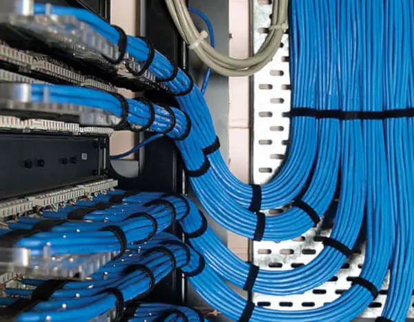
Data cabling is used to transmit electronic information from a source to a destination. Extensively used in computer and telecommunication systems the type of data cabling is either copper or fiber-optics.
The Golden Rules of Data Cabling
If your cabling is not designed and installed properly, you will have problems that you can’t even imagine.
What follows is a list of rules to consider when planning structured-cabling systems:
- Networks never get smaller or less complicated.
- Build one cabling system that will accommodate voice and data.
- Always install more cabling than you currently require. Those extra outlets will come in handy someday.
- Use structured-cabling standards when building a new cabling system. Avoid anything proprietary!
- Quality counts! Use high-quality cabling and cabling components. Cabling is the foundation of your network; if the cabling fails, nothing else will matter. For a given grade or category of cabling, you’ll see a range of pricing, but the highest prices don’t necessarily mean the highest quality. Buy based on the manufacturer’s reputation and proven performance, not the price.
- Don’t scrimp on installation costs. Even quality components and cable must be installed correctly; poor workmanship has trashed more than one cabling installation.
- Plan for higher-speed technologies than are commonly available today. Just because 1000Base-T Ethernet seems unnecessary today does not mean it won’t be a requirement in 5 years.
- Documentation, although dull, is a necessary evil that should be taken care of while you’re setting up the cabling system. If you wait, more pressing concerns may cause you to ignore it.
Always use reliable cabling
We cannot stress enough the importance of reliable cabling. Two recent studies vindicated our evangelical approach to data cabling. The studies showed:
- Data cabling typically accounts for less than 10 percent of the total cost of the network infrastructure.
- The life span of the typical cabling system is upward of 16 years. Cabling is likely the second most long-lived asset you have (the first being the shell of the building).
- Nearly 70 percent of all network-related problems are due to poor cabling techniques and cable-component problems.
If you have installed the proper category or grade of cable, the majority of cabling problems will usually be related to patch cables, connectors, and termination techniques. The permanent portion of the cable (the part in the wall) will not likely be a problem unless it was damaged during installation.
Of course, these were facts that we already knew from our own experiences. We have spent countless hours troubleshooting cabling systems that were nonstandard, badly designed, poorly documented, and shoddily installed. We have seen many dollars wasted on the installation of additional cabling and cabling infrastructure support that should have been part of the original installation.
Regardless of how you look at it, cabling is the foundation of your network. It must be reliable!
Data Cabling and speed
The past few years have seen some tremendous advances not only in networking technologies but also in the demands placed on them. In the past 30 years, we have seen the emergence of standards for 10Mb Ethernet, 16Mb Token Ring, 100Mb FDDI (Fiber-Distributed Data Interface), 100Mb Ethernet, 155Mb ATM (Asynchronous Transfer Mode), 655Mb ATM, 1Gb Ethernet, 2.5Gb ATM, 10Gb Ethernet, 40Gb Ethernet, and 100Gb Ethernet. Network technology designers are already planning technologies to support data rates of up to 400Gbps.
The average number of nodes on a network segment has decreased dramatically, whereas the number of applications and the size of the data transferred have increased dramatically. Applications are becoming more complex, and the amount of network bandwidth required by the typical user is increasing. Is the bandwidth provided by some of the new ultra-high-speed network applications (such as 10Gb Ethernet) required today? Maybe not to the desktop, but network backbones already take advantage of them.
Does the fact that software applications and data are putting increasing demands on the network have anything to do with data cabling? You might think that the issue is related more to network interface cards, hubs, switches, and routers but, as data rates increase, the need for higher levels of performance on the cable also increases.
Types of Communications Media
Four major types of communications media (cabling) are available for data networking today:
- unshielded twisted-pair (UTP),
- shielded or screened twisted-pair (STP or ScTP),
- coaxial,
- fiber-optic (FO).
It is important to distinguish between backbone cables and horizontal cables. Backbone cables connect network equipment such as servers, switches, and routers and connect equipment rooms and telecommunications rooms. Horizontal cables run from the telecommunications rooms to the wall outlets. For new installations, multistrand fiber-optic cable is essentially universal as backbone cable. For the horizontal, UTP accounts for 85 percent of the market for typical applications. Much of the focus of this book is on UTP cable; however, newer fiber optic–based network topologies are covered as well, as they are providing more and more advantages over UTP.
Twisted-Pair Cable
In traditional installations, the most economical and widely installed cabling today is twisted-pair
wiring. Not only is twisted-pair wiring less expensive than other media, installation is also simpler, and the tools required to install it are not as costly. Unshielded twisted-pair (UTP) and shielded twisted-pair (STP) are the two primary varieties of twisted-pair on the market today. Screened twisted-pair (ScTP) is a variant of STP.
Unshielded Twisted-Pair (UTP)
Though it has been used for many years for telephone systems, unshielded twisted-pair (UTP) for LANs first became common in the late 1980s with the advent of Ethernet over twisted-pair wiring and the 10Base-T standard. UTP is cost-effective and simple to install, and its bandwidth capabilities are continually being improved. (Read the UTP main article)
Shielded Twisted-Pair (STP)
Shielded twisted-pair (STP) cabling was first made popular by IBM when it introduced type classification for data cabling. Though more expensive to purchase and install than UTP, STP offers some distinct advantages. The current ANSI/TIA-568-C cabling standard recognizes IBM Type 1A horizontal cable, which supports frequency rates of up to 300MHz, but does not recommend it for new installations. STP cable is less susceptible to outside electromagnetic interference (EMI) than UTP cabling because all cable pairs are well shielded.
Screened Twisted-Pair (ScTP)
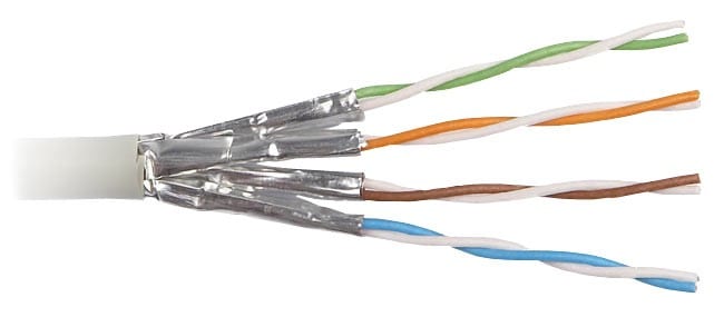
A recognized cable type in the ANSI/TIA-568-C standard is screened twisted-pair (ScTP) cabling, a hybrid of STP and UTP cable. ScTP cable contains four pairs of unshielded 24 AWG, 100 ohm wire (see Figure 1.3) surrounded by a foil shield or wrapper and a drain wire for grounding purposes. Therefore, ScTP is also sometimes called foil twisted-pair (FTP) cable because the foil shield surrounds all four conductors. This foil shield is not as large as the woven copper-braided jacket used by some STP cabling systems, such as IBM types 1 and 1A. ScTP cable is essentially STP cabling that does not shield the individual pairs; the shield may also be smaller than some varieties of STP cabling.
Screened Shielded Twisted-Pair (S/STP or S/FTP)
S/STP cabling, also known as screened fully shielded twisted-pair (S/FTP), contains four individually shielded pairs of 24 AWG, 100 ohm wire surrounded by an outer metal shielding covering the entire group of shielded copper pairs. This type of cabling offers the best protection from interference from external sources and also eliminates alien crosstalk (discussed later), allowing the greatest potential for higher speeds.
Category 7 and 7A are S/STP cables standardized in ISO 11801 Ed. 2.2, which offers a usable bandwidth to 600 and 1,000MHz, respectively. Its intended use is for the 10 Gigabit Ethernet, 10GBase-T application. S/STP cable looks similar to the cable in Figure 1.2 but has four individually shielded conductor pairs.
Fiber-Optic Cable
As late as 1993, it seemed that in order to move toward the future of desktop computing, businesses would have to install fiber-optic cabling directly to the desktop. It’s surprising that copper cable (UTP) performance continues to be better than expected. Fiber-optic cable is discussed in more detail in Chapter 8, “Fiber-Optic Media.”
Single-Mode Fiber-Optic Cable
Single-mode fiber-optic cable is most commonly used by telephone companies in transcontinental links and in data installations as backbone cable interconnecting buildings. Single-mode fiberoptic cable is not used as horizontal cable to connect computers to hubs and is not often used as a cable to interconnect telecommunications rooms to the main equipment room. The light in a single-mode cable travels straight down the fiber (as shown in Figure 1.5) and does not bounce off the surrounding cladding as it travels. Typical single-mode wavelengths are 1,310 and 1,550 nanometers.
Multimode Fiber-Optic Cable
Multimode fiber (MMF) optic cable is usually the fiber-optic cable used with networking applications such as 10Base-FL, 100Base-F, FDDI, ATM, Gigabit Ethernet, a10 Gigabit Ethernet, 40 Gigabit Ethernet, and 100 Gigabit Ethernet that require fiber optics for both horizontal and backbone cable. Multimode cable allows more than one mode (a portion of the light pulse) of light to propagate through the cable. Typical wavelengths of light used in multimode cable are 850 and 1,300 nanometers. Read the main article: Multimode fiber-optics.
Coaxial Cable
At one time, coaxial (or just coax) cable was the most widely used cable type in the networking business. Specifications for coax are now included in ANSI/TIA-568-C.4. This Standard consolidates information from the Residential (RG6 & RG59) and Data Center (Type 734 & 735) Standards. It is still widely used for closed-circuit TV and other video distribution and extensively in broadband and CATV applications. However, it is falling by the wayside in the data networking arena. Coaxial cable is difficult to run and is generally more expensive than twisted-pair cable. In defense of coaxial cable, however, it provides a tremendous amount of bandwidth and is not as susceptible to outside interference as is UTP. Overall installation costs might also be lower than for other cable types because the connectors take less time to apply. Although we commonly use coaxial cable to connect our televisions to our set-top boxes, we will probably soon see fiber-optic or twisted-pair interfaces to television set-top boxes.
Materials Used for Wire Insulation
A variety of insulating materials exists, including polyolefin (polyethylene and polypropylene), fluorocarbon polymers, and PVC.
The manufacturer chooses the materials based on the material cost, flame-test ratings, and desired transmission properties. Materials such as polyolefin are inexpensive and have great transmission properties, but they burn like crazy, so they must be used in combination with material that has better flame ratings. That’s an important point to keep in mind: don’t focus on a particular material. It is the material system selected by the manufacturer that counts. A manufacturer will choose insulating and jacketing materials that work together according to the delicate balance of fire resistance, transmission performance, and economics.
The most common materials used to insulate the wire pairs in Category 5e and greater plenum-rated cables are fluorocarbon polymers. The two varieties of fluorocarbon polymers used are fluorinated ethylene-propylene (FEP) and perfluoroalkoxy (PFA).
These polymers were originally developed by DuPont and are also sometimes called by their trademark, Teflon. The most commonly used and most desirable of these materials is FEP. Over the past few years, the demand for plenum-grade cables exceeded the supply of available FEP. During periods of FEP shortage, Category 5e plenum designs emerged that substituted another material for one or more of the pairs of wires. In addition, some instances of marginal performance occurred in the UL-910 burn test for plenum cables. These concerns, coupled with increases in the supply of FEP and substitutes like MFA, have driven these designs away.
Insulation Colors
The insulation around each wire in a UTP cable is color-coded. The standardized color codes help the cable installer make sure each wire is connected correctly with the hardware. In the United States, the color code is based on 10 colors. Five of these are used on the tip conductors, and five are used on the ring conductors. Combining the tip colors with the ring colors results in 25 possible unique pair combinations. Thus, 25 pair groups have been used for telephone cables for decades.
Note: The words tip and ring hark back to the days of manual switchboards. Phono-type plugs were plugged into a socket to connect one extension or number to another. The plug had a tip, then an insulating disk, and then the shaft of the plug. One conductor of a pair was soldered into the tip and the other soldered to the shaft, or ring. Remnants of this 100-year-old technology are still with us today.
The following table lists the color codes found in a binder group (a group of 25 pairs of wires) in larger capacity-cables. The 25-pair cable is not often used in data cabling, but it is frequently used for voice cabling for backbone and cross-connect cable.
| Pair Number | Tip Color | Ring Color |
| 1 | White | Blue |
| 2 | White | Orange |
| 3 | White | Green |
| 4 | White | Brown |
| 5 | White | Slate |
| 6 | Red | Blue |
| 7 | Red | Orange |
| 8 | Red | Green |
| 9 | Red | Brown |
| 10 | Red | Slate |
| 11 | Black | Blue |
| 12 | Black | Orange |
| 13 | Black | Green |
| 14 | Black | Brown |
| 15 | Black | Slate |
| 16 | Yellow | Blue |
| 17 | Yellow | Orange |
| 18 | Yellow | Green |
| 19 | Yellow | Brown |
| 20 | Yellow | Slate |
| 21 | Violet | Blue |
| 22 | Violet | Orange |
| 23 | Violet | Green |
| 24 | Violet | Brown |
| 25 | Violet | Slate |
With LAN cables, it is common to use a modification to this system known as positive identification. PI, as it is sometimes called, involves putting either a longitudinal stripe or circumferential band on the conductor in the color of its pair mate. In the case of most four-pair UTP cables, this is usually done only to the tip conductor because each tip conductor is white, whereas the ring conductors are each a unique color.
The next table lists the color codes for a four-pair UTP cable. The PI color is indicated after the tip color.
| Pair Number | Tip Color | Ring Color |
| 1 | White/Blue | Blue |
| 2 | White/Orange | Orange |
| 3 | White/Green | Green |
| 4 | Withe/Brown | Brown |
Twists
When you slice open a UTP communications cable, you will notice that the individual conductors of a pair of wire are twisted around one another. At first, you may not realize how important these twists are.
Did you know that in Category 5e cables a wire pair untwisted more than half of an inch can adversely affect the performance of the entire cable?
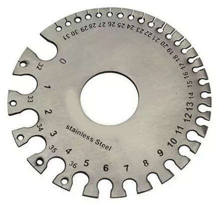
Wire Gauge
Copper-wire diameter is most often measured by a unit called AWG (American Wire Gauge). Contrary to many other measuring systems, as the AWG number gets smaller, the wire diameter actually gets larger; thus, AWG 24 wire is smaller than AWG 22 wire. Larger wires are useful because they have more physical strength and lower resistance.
However, the larger the wire diameter, the more copper is required to make the cable. This makes the cable heavier, harder to install, and more expensive.
The cable designer’s challenge is to use the lowest possible diameter wire (reducing costs and installation complexity) while at the same time maximizing the wire’s capabilities to support the necessary power levels and frequencies.
Category 5e UTP is always 24 AWG; IBM Type 1A is typically 22 AWG. Patch cords may be 26 AWG, especially Category 3 patch cords. The evolution of higher-performance cables such as Category 6 and Category 6A has resulted in 23 AWG often being substituted for 24 AWG.
The following table shows 22, 23, 24, and 26 AWG sizes along with the corresponding diameter, area, and weight per kilometer.
| AWG | Nominal Diameter (in) | Nominal Diameter (mm) | Circular-Mil (cm) | Area (mm2) | Weight (Kg/Km) |
| 22 | 0.0253 | 0.643 | 640.4 | 0.3256 | 2.895 |
| 23 | 0.0226 | 0.574 | 511.5 | 0.2581 | 2.295 |
| 24 | 0.0201 | 0.511 | 404.0 | 0.2047 | 1.82 |
| 26 | 0.0159 | 0.404 | 253.0 | 0.1288 | 1.145 |
The dimensions in the previous table were developed more than 100 years ago. Since then, the purity and therefore the conductive properties of copper have improved due to better copper-processing techniques. Specifications that cover the design of communications cables have a waiver on the actual dimensions of a wire. The real concern is not the dimensions of the wire, but how it performs, specifically with regard to resistance in ohms. The AWG standard indicates that a 24 AWG wire will have a diameter of 0.0201″, but based on the performance of the material, the actual diameter of the wire may be slightly less or slightly more (but usually less).
Solid Conductors vs. Stranded Conductors
UTP cable used as horizontal cable (permanent cable or cable in the walls) has a solid conductor, as opposed to patch cable and cable that is run over short distances, which usually have stranded conductors. Stranded-conductor wire consists of many smaller wires interwoven together to form a single conductor.
Cable Length
The longer the cable, the less likely the signal will be carried completely to the end of the cable because of noise and signal attenuation. Realize, though, that for LAN systems the time it takes for a signal to get to the end is also critical.
Cable design engineers are now measuring two additional performance parameters of cable: the propagation delay and the delay skew. Both parameters are related to the speed at which the electrons can pass through the cable and the length of the wire pairs in the cable.
To learn more about how to plan your data cabling structure we recommend the following book: