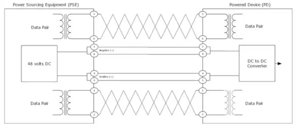
To understand how Power over Ethernet works we have to look at the standard. The PoE standard defines a method for powering a PD (Powered Device) over a cable by Power Sourcing Equipment and then removing power when the PD is disconnected. The formal process includes an idle state and three operational states: detection, classification, and operation.
The PSE leaves the cable unpowered (idle state) while it periodically checks to determine if a PD has been connected to the cable. This process is called detection.
Once a PD (Powered Device) has been detected, the PSE (Power Sourcing Equipment) may execute a probing process, called classification, to determine the current levels needed by the PD. If the PSE has enough power, then it begins the operation phase by powering the PD. It then monitors the power levels to ensure that the PD is still connected.
Power Detection
There are several challenges when it comes to providing power over an Ethernet cable, with the first being: how do you know what’s at the other end of the cable? If you just provide power without checking, you could damage any non-PoE equipment that might be attached to the end of the cable.
After all, there’s no guarantee that the twisted-pair cable you are powering is connected to an Ethernet device. The cable might be connected to an analog telephone instead, which might be sensitive to power on its cable connection. If an installer tries one cable after another in an attempt to get something to work (which is not an uncommon approach), then a powered cable could cause a problem when connected to something that isn’t an Ethernet device.
To avoid placing power on the link unless there is a Powered Device connected to the other end of that link, the standard provides a method, called power detection, for detecting the presence of a Powered Device. Once a Powered Device is detected, then another set of mechanisms, called power classification, can be used to determine what power level is needed by the PD.
Power detection is performed by the Power Sourcing Equipment, which periodically monitors the Ethernet link for the presence of a Powered Device at the other end. This is done by applying a small voltage (2.70 V to 10.1 V) to the cable pairs and measuring the current flow, looking for the presence of a 25,000-ohm resistance provided by the PD as a signal that it is present.
A low voltage is used for detection because it is unlikely to cause damage to devices not designed for PoE that might be connected to the link. If a 25,000-ohm resistance is detected on the cable pairs, then this is considered a valid PD signature, indicating the presence of a Powered Device at the other end of the link. The next thing that the PSE does is to determine how much power to send over the link.
Power Classification
After the PD is detected, the PSE (Power Sourcing Equipment) and PD (Powered Device) can interact to determine how much power the PD requires. There are two power classification mechanisms that are used: physical layer classification and data link layer classification. Type 2 PDs that require more than 13.0 watts must support data link layer classification, which is optional for all other devices. If both classification systems are supported by the PSE and the PD, then the information provided by data link layer classification takes precedence over that from the physical layer classification.
If a PSE has multiple ports, then the typical approach is to probe one port at a time, classify the power required, ramp up the power to the required amount, and move on to the next port until all the power that can be provided by the PSE is allocated. This makes it possible to bring up a port at the full power level supported for a Type 2 PD, for example, and then negotiate the actual power level needed by the PD using the data link layer classification system.
Physical layer classification method
The physical layer classification was defined in the original 802.3af system, and all Type 1 PSEs may optionally use the physical layer classification system to classify the power requirements of the PD. If the Type 1 PSE doesn’t support classification, then it simply provides the full power level of 15.4 watts whenever it detects a Powered Device. While that provides the simplest method of automatic PoE operation, most vendors use PSE controller chips that provide a power management capability to classify the power requirements on a link.
The physical layer classification process occurs before a PSE provides power to the PD over the link. The process consists of the PSE applying a reduced voltage (between 15.5 V and 20.5 V) into the cable pairs, and measuring which one of a limited set of currents is being drawn by the Powered Device. The specific current detected is used as a signal provided by the PD to inform the PSE as to the current requirements of the PD.
This makes it possible for the PSE to determine which of several current levels is required by the Powered Device before actually providing the full voltage and power levels to the link. After the classification process completes, there is a “ramp up” process that increases the power to the level determined by the classification process.
The following table shows the five power classifications defined in the standard. If the Type 1 PSE does not support classification, then it must assign all PDs to Class 0, which is 15.4 watts.
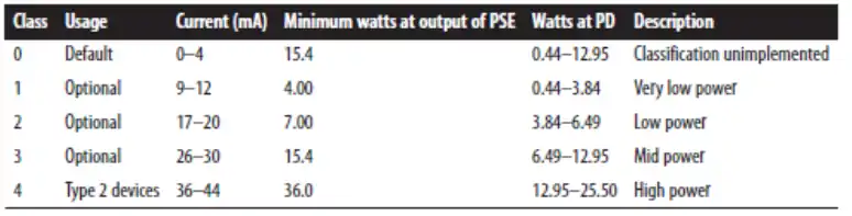
A Type 2 PD presents a signature that indicates that it is a Class 4 device. A Type 1 PSE will treat a Type 2 PD as a Class 0 device, and provide 15.4 watts if it has the power available. A Type 2 PSE will interact with a Type 2 PD such that both ends detect a Class 4 device; the PD will know that it is connected to a high-power PSE and may draw up to 25.5 watts. A Type 2 PD that does not receive the Class 4 Physical Layer signatures may choose not to start, or must start at a power level of 13 watts and request more power via the data link layer classification system after startup.
Data link layer classification method
The 802.3at extension to the standard defines a separate classification mechanism called data link layer classification that is based on the Link Layer Discovery Protocol (LLDP), transmitting LLDP packets with “Organizationally Specific TLVs” (where TLV stands for type-length-value). These packets are defined in Clause 79 of the 802.3 standard.
The LLDP packets allow the network management functions supported by the PSE and PD to advertise and discover the power requirements of the Powered Device. The 802.3at extension defines LLDP information packets that can advertise this information between the PD and the PSE.
Type 2 devices are required to do both Type 1 physical layer classification and the data link layer classification. The Type 2 device will use the physical layer classification system to identify itself as a Class 4 device, requiring high power. The Type 2 Powered Device must not draw more than 13 watts if it has not received a Type 2 Class 4 Physical Layer signal.
Type 2 powered devices that can operate with less than 12.95 watts must be able to be powered by a Type 1 PSE. If a Type 2 PD cannot operate at less than 12.95 watts, when connected to a Type 1 PSE it must indicate to the user that there is not sufficient power available over the link for the device to function correctly.
The LLDP packet exchanges also provide an optional capability to dynamically adjust power requirements after the initial detection and classification phases. Dynamically adjusting power can help manage the total amount of power that must be provided by a PoE switch on its Ethernet ports to meet the needs of the PDs, making the system more efficient. Note that the dynamic power changes are not designed for rapid variations; a PSE may take as much as 10 seconds to respond to a requested power change.
Mutual identification
The interrogation and power classification functions make it possible for the PSE and PD to provide “mutual identification,” in which each determines whether it is connected to a Type 1 or Type 2 device. Mutual identification also provides useful information for devices that support power management features instead of purely automatic PoE.
If a PD or PSE does not implement classification, it will not be able to complete a mutual identification process and will only be able to perform as a Type 1 device.
Link Power Maintenance
Once the detection and classification processes have been completed, then the PoE link is operational and the PSE is providing power over the link. The PD provides a maintained power signature (MPS) consisting of both the current draw used by the PD and a specified input impedance, which can be sensed on the cable pairs by the PSE.
This makes it possible for the PSE to monitor the link for the continued presence of an active PD. If loss of MPS is detected, then the PSE will quickly remove power from the link and return to the detection process of monitoring the link for the presence of a PD.
Power Fault Monitoring
While providing power, the PSE also monitors the link for various fault conditions, including under- and over-voltage conditions and under- and overcurrent conditions.
When any of these conditions is detected, the PSE will shut off DC power to the link and go back to the power detection phase.
Power shutoff is designed to happen rapidly, in a maximum of one-half second. This helps to avoid supplying power to a cable that has been disconnected and is then quickly reconnected to a different port in the cabling system.
To learn more about Power over Ethernet you should also read these articles:
- Power over Ethernet Main Article (What is PoE?)
- PoE Device Roles and Type Parameters
- PoE and Cable Pairs
- Power over Ethernet Port Management
- Vendor Extensions to the Standard (PoE)
References and Credits
Ethernet: The Definitive Guide: Designing and Managing Local Area Networks, by Charles E. Spurgeon and Joann Zimmerman (chapter 6)