The PoE standard specifies the way that power is injected into the Ethernet cable pairs, and which pairs should be used. Power is injected using one pair of wires to carry the positive current (“plus”), and a second pair to carry the negative (“minus”). This provides two wires to carry the positive power and two wires for the negative power, which helps reduce resistance and heating effects. The standard defines two alternatives for which cable pairs are used. If you are looking for our PoE main article click here.
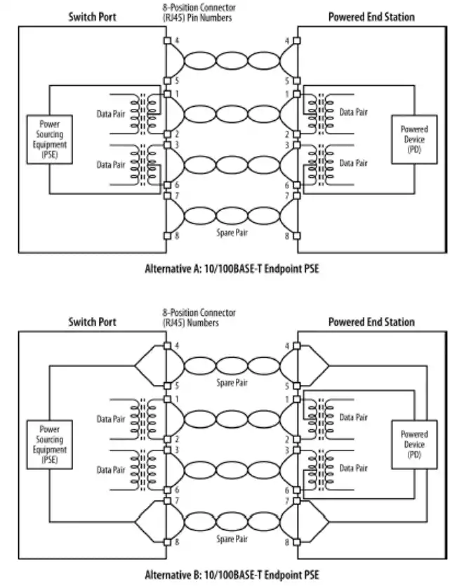
Alternative A uses the data signal pairs (wires connected to pins 1,2 and 3,6). Power is placed on the data pairs by connecting the DC power supply to a center tap on the internal signal coupling transformers, an approach that is also called “phantom power.”
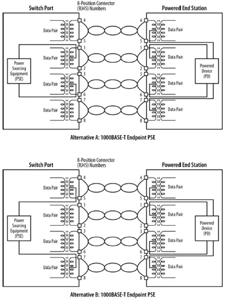
Alternative B uses the “spare” pairs (wires connected to pins 4,5 and 7,8). The spare pairs are so-called because they do not carry data signals in the 10BASE-T and 100BASET systems. When the spare pairs are used, the power is coupled directly to the wire pairs, with no need for a transformer. Note that all four pairs are used to carry signals in the 1000BASE-T systems, meaning that transformer coupling is used on all four wire pairs and that the only difference between Alternatives A and B in 1000BASE-T systems is the choice of cable pairs that are used.
For a power sourcing device, either alternative can be used under the current PoE standard, but not both. The Powered Device must be able to accept power on either the Alternative A or the Alternative B wiring scheme, as the PD cannot know which pairs the PSE may use.
Also, the PD must be able to accept either current polarity (positive or negative) on a given wire pair. That’s because there is no way to guarantee which polarity of power will end up on which PD wire pairs, given that the switch port may implement automatic signal crossover (MDI-X), or that a patch cable wired to provide a crossover may be present in any given Ethernet link. Therefore, the PD contains circuitry that automatically accommodates all possible wiring variations with respect to which pairs are carrying DC power, as well as all possible variations with respect to the polarity of the current carried by any given pair.
As shown in the figure below, the 10BASE-T and 100BASE-T standards use only two pairs, 1,2 and 3,6.
The next figure shows that the 1000BASE-T standard uses all four pairs.
The wiring schemes used for midspan devices look much the same, with the major difference being that the midspan device is inserted in the cabling path between the Ethernet switch and the Powered Device. The midspan device contains the DC power supply and injects the power into the Ethernet link using the same Alternative A and B wiring schemes as for 10/100BASE-T and 1000BASE-T links.
PoE and Ethernet Cabling
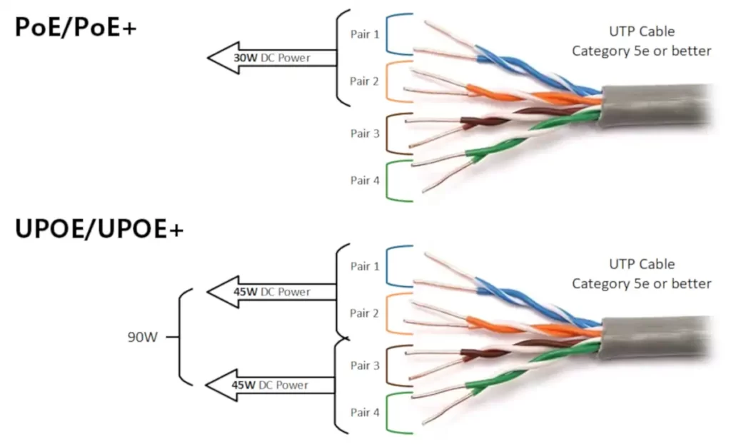
The original 802.3af PoE standard was designed to operate over Category 3 cabling, which was defined as having two pairs available for use by Ethernet signals. The 802.3at extension to the PoE standard specifies Category 5e cabling or better. This is more formally referenced as Class D or better cabling, as specified in the international ISO/IEC 11801:1995 standard.
One technical issue with Power over Ethernet is that it causes a small amount of heating of the cable to occur, due to the resistance of the copper wires interacting with the DC power being carried over the wires. The slightly elevated temperatures do not present any safety risk, or risk of damage or premature aging of the cables or connectors.
When many cables are bundled together and all cables are carrying maximum amounts of PoE power, however, the small amount of heating becomes more significant in that it could affect the signal-carrying characteristics of the cables in the bundle. Along these lines, it’s important to note that Category 6 and 6A cabling both have thicker copper wires than Category 5, and that thicker wire results in lower resistance to DC currents and therefore significantly less heating. Some tests indicate that the amount of heating in Cat6/6A cables is approximately 50% less than in Cat5/5e cables. By the way, tests also show that there is no problem using shielded twisted-pair cables to carry PoE and that the foil or stranded shielding actually helps the cable to dissipate any heating effects.
Modifying cabling specifications
The development of the 802.3at standard included careful consideration of what happens in large cable bundles with PoE enabled on all cables. However, the cabling standards are not part of the IEEE standards, and cabling specifications are not the responsibility of the IEEE. The IEEE standard does note that:
Under worst-case conditions, Type 2 operation requires a 10°C reduction in the maximum ambient operating temperature of the cable when all cable pairs are energized or a 5°C reduction in the maximum ambient operating temperature of the cable when half of the cable pairs are energized. Additional cable ambient operating temperature guidelines for Type 2 operation are provided in ISO/IEC TR29125 and TIA TSB-184.2
As a result of these considerations, one recommendation is to avoid high temperatures around the cable bundles and to ensure that the operating temperature around cable bundles does not exceed 50°C (122°F).
The cabling considerations for PoE are described in separate standards documents. The two documents cited by the IEEE include a technical bulletin entitled “TSB-184 Guidelines for Supporting Power Delivery Over Balanced Twisted-Pair Cabling,” which is available from the Telecommunications Industry Association, and an ISO standards document called ISO/IEC TR 29125, “Information technology—Telecommunications cabling requirements for remote powering of terminal equipment,” which is available from the ISO. Both documents provide guidance to cable installers to help characterize
the amount of heating that can be expected in the worst case (large bundles with lots of cables carrying power) and to ensure that a cabling system will work optimally when PoE is in use.
The bottom line is that a small amount of heating occurs on any copper cable that carries power. The heating is not an issue for individual Ethernet cables, but when those cables are bundled tightly together in a cabling system, and if all cables are carrying the maximum amounts of power, then the increase in temperature could have an effect on signal quality, especially if the ambient temperature around the cables is already very high. Under normal circumstances with cables inside a typical office building, the cables will function correctly.
PoE Power Management
An Ethernet switch that provides PoE over some or all of its ports can also provide a power management point for the network devices powered over the Ethernet links. While the PoE standard defines the mechanisms for sending direct current power over Ethernet cables, it does not define which options and other management capabilities vendors may implement in the equipment that they build. Nor does it define how those management functions may be designed, or what the management commands may look like. Assuming that a management interface is provided, the documentation for your switch or midspan equipment is your source for the details on how the interface is organized and what commands it uses.
As the PoE standard is defined to operate automatically, it’s possible for a low-cost switch to provide a simple PoE capability that supports PoE operations but does not provide any management interface. However, many vendors do provide a management interface on the PSE that allows you to do such things as control which ports provide power, turn power on and off on a given port, and monitor power consumption per port.
PoE Power Requirements
As a user of PoE, it is important to understand that the power supply in the Ethernet switch or multi-port midspan device will be a limiting factor. In other words, you cannot provide more PoE power than the internal power supply of the PSE can handle. It’s up to you to make sure that the PSE—typically an Ethernet PoE switch—has enough power to meet your needs.
For example, a 24-port switch providing 802.3af PoE at 15.4 watts per port requires an extra 370 watts of power beyond what is required to run the Ethernet switching functions in order to provide power to all 24 PoE ports simultaneously. If those ports each provide 30 watts of 802.3at power, then the switch will need 720 watts of extra power capability for the PoE ports.
To learn more about Power over Ethernet you should also read these articles:
- Power over Ethernet (main article)
- PoE Device Roles and Type Parameters
- Power over Ethernet (PoE) Operations
- Power over Ethernet Port Management
- PoE Vendor Extensions
References and Credits
Ethernet: The Definitive Guide: Designing and Managing Local Area Networks, by Charles E. Spurgeon and Joann Zimmerman (chapter 6)