Definition of Synchronous Optical Network (SONET) in the Network Encyclopedia.
What is Synchronous Optical Network (SONET)?
SONET stands for Synchronous Optical Network is a physical layer specification for broadband synchronous transmission of voice, video, and data over long distances of fiber-optic cabling at speeds of more than 1 Gbps. Synchronous Optical Network (SONET) networks can carry voice, video, and data simultaneously and are often used by telecommunications providers to provide the underlying transport mechanism for Asynchronous Transfer Mode (ATM) networking in internal telco and long-distance carrier networks. SONET can also be used as the underlying transport for Fiber Distributed Data Interface (FDDI), Integrated Services Digital Network (ISDN), and Switched Multimegabit Data Services (SMDS) communication.

SONET was developed by Bellcore in the mid-1980s and has been standardized by the American National Standards Institute (ANSI). A European version called Synchronous Digital Hierarchy (SDH), which has been standardized by the International Telecommunication Union (ITU), is essentially equivalent to SONET.
How It Works
SONET is built from multiplexed DS0, DS1, or DS3 digital signal channels using optical time-division multiplexing (TDM) to form a single Synchronous Transport Signal (STS) link for communication. The basic SONET transmission rate is 810 bytes transmitted every 125 microseconds, and frames are transmitted whether or not a payload (data) is present. A standard STS-1 SONET data path thus consists of 810 DS0 channels, of which 783 are used for data transmission and 27 are used for framing, error correction, format identification, and other forms of overhead.
SONET is usually implemented as a dual-ring topology to provide redundancy and fault tolerance. These rings are usually self-healing within 50 milliseconds of a break. SONET speeds are classified by one of the following:
- Electrical signal speeds called Synchronous Transport Signal (STS)
- Optical carrier line speeds called optical carrier (OC)
The following table shows the currently defined SONET speeds.
SONET Speeds
| Electrical Signal | Optical Carrier | Speed |
| STS-1 | OC-1 | 51.48 Mbps |
| STS-3 | OC-3 | 155.52 Mbps |
| STS-12 | OC-12 | 622.08 Mbps |
| STS-24 | OC-24 | 1.24 Gbps |
| STS-48 | OC-48 | 2.48 Gbps |
| STS-192 | OC-192 | 9.95 Gbps |
SONET configuration issues
These parameters affect the configuration of SONET devices:
- Clocking – The clocking default value is line, and is used whenever clocking is derived from the network. The clock source internal command is typically used when two Cisco 12000 Series Internet Routers are connected back-to-back, or are connected over dark fiber where no clocking is available. In either case, each device must have its clock source set to internal. For a more detailed explanation, refer to Configuring Clock Settings on POS Router Interfaces.
- Loopback – Loopback is a line and internal (DTE) value. This is a SONET section loopback if done on the controller. If done on the individual interface, these are individual path loopbacks.
- Framing – Most Cisco framers support both SONET and SDH.
- Payload scrambling – This value is normally set to On.
- S1S0 flag – This value must be between 0 and 3; the default value is 0. With SONET, s1so must be set to 0, and with SDH it must be set to 2. Value 3 corresponds to the received Alarm Indication Signal (AIS).
- J0 flag – 0-255 – This setting is the section trace identifier. It is only required for section tracing.
- C2 flag – 0-255 – This setting specifies the STS path signal label (5 to 7 are configured with the pos flag command).
- Alarm reporting – Alarm reporting allows you to specify which alarms are reported. The permitted values are b1-tca, b2-tca, sf-ber, sd-ber, los, lof, ais-l, and rdi-l. (This value is configured with the pos report command).
- Alarm thresholds – The alarm threshholds setting specifies the Bit Error Rate (BER) thresholds that signal an alarm. (This value is configured with the pos threshold command).
Debugging Synchronous Optical Network
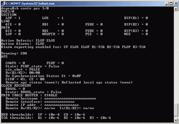
If the link is down/down, check for active alarms and defects. Troubleshooting, in this case, is essentially the same as serial troubleshooting. If you look at the SONET controller, it can provide plenty of L1 and SONET information. Defects and alarms in SONET are similar to the same alarms when you troubleshoot and diagnose T1/E1 and T3/E3 (LOS, LOF, AIS (Blue Alarm), and so on) issues.
Active defects and active alarms fields show the current status of the POS controller, and point to the problem.
The numbers for errors under the Section, Line, and Path are accumulators, and tell you the number of times the condition has occurred; these numbers do not indicate if the error is currently happening.
Bit Interleaved Parity (BIP) errors are parity errors that correspond to a specific SONET layer: BIP(B1) corresponds to Line, BIP(B2) to the Section, and BIP(B3) to the Path layer parity errors.
When you look at the output of the show controllers pos x/y command, pay attention to which SONET layers accumulate errors: SONET Line, Section, or Path. When you troubleshoot SONET problems or errors, the first thing to do is to isolate the bad section.
