Fiber optic technology is increasingly present in our daily lives. In this article, we intend to approach the different aspects of this technology. Starting with the types of optic fiber, we will also address the loss factors and the fiber filter technology.
You can also use our index to jump right to your topic of interest.
Index
Let’s start by identifying the main components of a fiber optic cable.
A fiber-optic cable has three components: a protective outer coating, an inner cladding, and a fiber core.
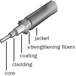
The cladding is of a different density than the core, so the light bounces against it. The fiber core is pre-soaked in chemicals to increase its transmission properties.
Optic fiber types and the difference between Multimode Fiber and Single-Mode Fiber
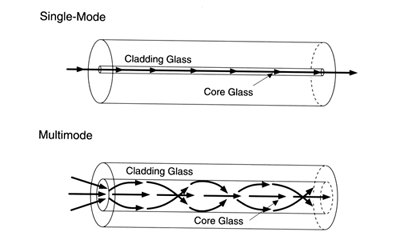
Telecom fiber is classified into two types of optic fiber: multimode and single-mode. The only physical difference between the two is the size of the core.
Because of the core size, the performance characteristics are different. With its smaller core, single-mode fiber can carry substantially more information than multimode. Also, single-mode fiber exhibits less loss than multimode.
Multimode fiber
Multimode is one type of optic fiber that allows many paths or modes for the light, but single-mode allows only one single path for the light. The larger core of multimode fiber allows light to break up into many different modes. Some modes will make it to the far end faster than others, causing the original signal to be broadened out in time. In time-division multiplexed (TDM) digital signal, the variety of light speed will limit the spacing between bits of information, and the rate at which bits can be sent.
This is known as dispersion.
Typical multimode rates are in the hundreds of megabits per second (Mbps). (Check the multimode fiber main article)
Single-mode Fiber
The other type of optic fiber, single-mode fiber, allows only one mode to travel down the fiber – right down the middle. The entire signal travels the length of the fiber at the same rate, allowing for much higher data rates. Typical single-mode rates are in the millions and billions of bits per second. (Check the single-mode fiber main article)
Fiber geometry
Fiber manufacturing continues to improve, making fiber less expensive and of better quality.
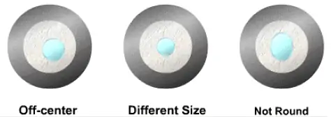
However, there are some allowable variations in the physical structure of the fiber. One of the most important characteristics related to splicing and testing is the shape and location of the core within the cladding.
Since light only travels in the core of the fiber, it is necessary for fiber cores to link up when splicing them. In some cases, the fiber cores may not match up well. They may be slightly off-center from the cladding center, a different size, or may not be round. However, in some cases, it may not be possible to make a splice better than 0.20 dB, due to the mismatch in fiber characteristics.
Loss factors
The next picture shows some of the lost factors in fiber. It shows only the core of the fiber because that is where the signal travels. After light leaves the core it cannot be recovered.
Connector Losses
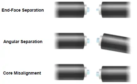
Connector loss depends on passing light from one core to another. Because a connector relies on the ability of the bulkhead to line up the two fiber ends, it allows for some different loss factors than the with field splices.
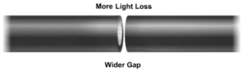
If two fiber ends are separated, loss occurs because of the spreading of light as it comes out of the first core.
Even when the gap is small, some light may be lost. The wider the gap, the more loss there will be.
If the bulkhead is worn and allows some play in the alignment of two fibers, some light may be lost because the cores are not lined up completely. Core misalignment is the same for splices.
See also: SC/ST connectors
Macrobending
A macrobend is a bend you can actually see. When you bend fiber, you can cause some of the light rays to exceed the critical angle, allowing light to leak out of the core and into the cladding. When light is in the cladding it cannot easily get back into the core; it then leaks out through the buffer.
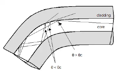
Macrobending loss is more severe at longer wavelengths. You can reduce macrobending by eliminating tight bends in the fiber and cable.
Microbending
Microbending produces the same effect as macrobending; it causes the light to exceed the critical angle and leak out of the core. It occurs on a microscopic scale and is not visible to the eye.
Microbending appears as a wrinkle in the fiber caused by temperature variations during manufacturing.
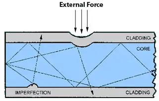
It can also be caused by extreme temperature swings in the installed cable when the different materials in the cable structure expand and contract at different rates. This causes the fiber to be squeezed or stretched, in turn causing microbending.
Absorption
Some light is always absorbed into the glass structure. Certain wavelengths exhibit higher absorption rates than others. Absorption can be neither changed nor controlled by the user. It is an intrinsic loss characteristic of the fiber.
The most serious absorption in glass occurs close to the operation wavelength “windows” of 1310 and 1550 nm. These areas often show high levels of absorption due to the OH ion, which is produced as a result of the manufacturing process. The absorption peaks can grow in certain conditions and cause increased attenuation in the operating wavelength windows.
Attenuation in optic fibers
In an optic fiber, Attenuation is caused by intrinsic factors, primarily scattering and absorption. Attenuation is also caused by extrinsic factors, including stress from the manufacturing process, the environment, and physical bending.
For a broader definition of attenuation read this article: What is attenuation in networking?
The most common form of scattering, Rayleigh scattering, is caused by small variations in the density of glass as it cools. These variations are smaller than the wavelengths used and, therefore, act as scattering objects. Scattering affects short wavelengths more than long wavelengths and limits the use of wavelengths below 800 nm.
Attenuation due to absorption is caused by the intrinsic properties of the material itself, the impurities in the glass, and any atomic defects in the glass. These impurities absorb the optical energy, causing the light to become dimmer. Whereas Rayleigh scattering is important at shorter wavelengths, intrinsic absorption is an issue at longer wavelengths.
The primary factors affecting attenuation in optic fibers are the length of the fiber and the wavelength of the light.
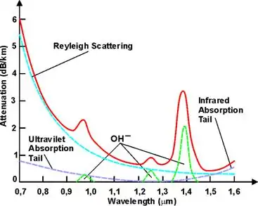
The next picture shows the loss in decibels per kilometer (dB/Km) by wavelength from Rayleigh scattering, intrinsic absorption, and total attenuation from all causes.
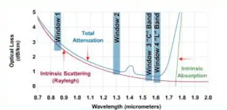
One good operation point is the local minimum of 1310 nm. Another good operation point is at 1550 nm, where the water peak is behind and Raleigh scattering is very low. If the wavelength is made any longer, infrared light is absorbed in the crystal lattice of the silica, fiber begins to behave as if opaque, and nothing goes through. The two choices of operation are 1310 or 1550 nm.
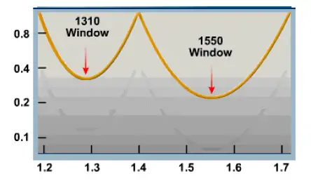
Spectral Attenuation
The spectral attenuation curve shows the wavelength dependence of loss factors. The following image shows the span of wavelength used in telecom fiber., from 600 to 1600 nm. The normal operating bands of wavelength
The effects of Rayleigh Scattering are decreased with longer wavelengths. UV absorption picks up at a longer wavelength and effectively limits the higher wavelength operations.
The OH peaks are case by absorption of light due to the OH ions created in the manufacturing process. They are also called water peaks because the OH ion is a component of water – H2O.
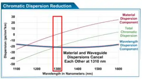
Dispersion
Dispersion causes the pulse to spread as it travels along the fiber. Modal dispersion limits the use of multimode fiber in short distances. However, chromatic dispersion is important for single-mode fiber. Dispersion levels depend on fiber type and laser used; degradation increases exponentially.
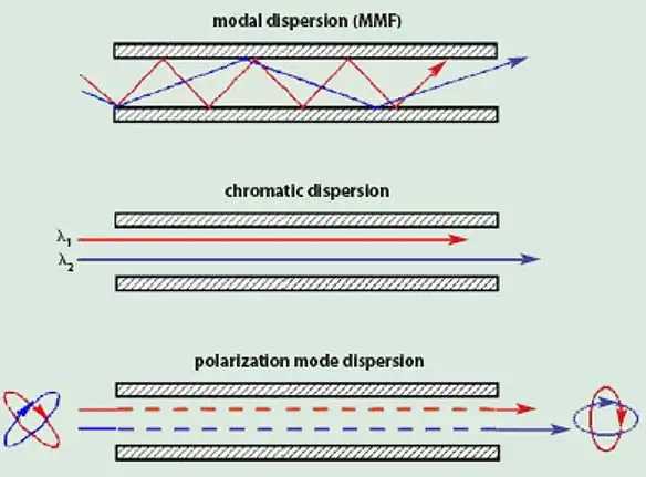
Chromatic and polarization mode dispersion both result in a spreading of the light pulse. With chromatic dispersion, different wavelengths, in an optical pulse, travel at different speeds and arrive at different times. With polarize mode dispersion, light spreads because of the difference in the propagation velocities of light in the orthogonal polarization states of the transmission medium.
Though chromatic dispersion is generally not an issue at speeds below OC-48, it does increase with higher bit rates because of the spectral width required. New types of zero-dispersion-shifted fibers greatly reduce these effects. The phenomenon can also be lessened with dispersion compensators.
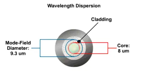
In waveguide dispersions, some of the light gets into the cladding and travels at a different speed. The effective diameter of light conduction is called the mode-field diameter, which is similar to a halo effect. For an 8-um score, the mode field diameter is 9.3 um, Material dispersion and waveguide dispersion actually cancel each other at the 1310-nm wavelength.
Fiber Capacity
One of the newer generations of fiber, such as nonzero dispersion-shifted fiber, is well suited for a combination of reasonably high-speed time-division multiplexing (TDM) and reasonably high channel count systems at the 1550 window.
Next-generation fibers, such as LEAF or TrueWave, which have been well optimized for very high capacity, create a great fiber plant for running both high-speed TDM and large-channel-count DWDM in the extended wavelength bands of both C and L.
High capacity can depend greatly upon the basic fiber used in the fiber plant. The principal characteristics of these different fibers.
Optical Filter Technology
Fiber Bragg grating and the dielectric filter are examples of optical filter technology.
These types of filters are used to identify different wavelengths or lambdas.
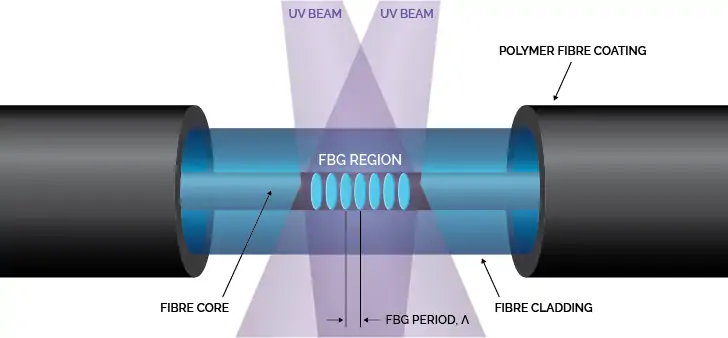
Fiber Bragg grating
Typically, channels are filtered using Fiber Bragg grating, which drops the appropriate channel by reflecting it out. Fiber Bragg grating may be built right into the fiber, it’s not necessary to terminate fiber. The Fiber Bragg grating may be built by bombarding the fiber with ultraviolet (UV) light through a mask or by using two UV beams that intersect and create an interference pattern on the fiber to be grated.
Optical Amplifier
The optical amplifier (OA) is a device that amplifies an input optical signal without converting it to electrical form. The OA provides four terahertz (THz) of optical bandwidth near 1550 nm, nearly ideal noise performance, low signal distortion and crosstalk, high-output saturation power, and it is simple and efficient. The optical pulse begins to deteriorate as it travels farther and farther. In order to prevent this deterioration, perform the 3Rs, namely – restore signal level, reshape pulse, and retime pulse.
Conclusion
In this article, we cover the most important aspects related to optic fiber including:
- The three main components of a fiber optic cable;
- The modes by which fiber optic cables are classified (types of optic fiber): single-mode and multimode;
- The lost factors in fiber including connector losses, macrobending, microbending, and absorption;
- Attenuation in optic fiber can be caused by scattering, absorption, stress from the manufacturing process, the environment, and physical bending;
- Dispersion causes the light pulse to spread as it travels along the fiber;
- The Optical Amplifier (OA) is a device that amplifies an input optical signal without converting it to an electric form.