Definition of Ethernet Switch in Network Encyclopedia.
What is Ethernet Switch?
Sometimes simply called a switch (when referring to Ethernet networking hardware), a networking component used to connect workgroup hubs to form a larger network or to connect stations that have high bandwidth needs.
Ethernet switches provide superior performance to hubs but are more expensive.
How it works
In a hub, which basically functions as a multiport repeater, a packet entering one port is regenerated and passed to every other port. As a result, if you try to connect several workgroup local area networks (LANs) by uplinking their hubs to a main hub, the new larger network remains a single collision domain. With the increased number of nodes on the network, more collisions will occur, and network traffic congestion can result. If a 10-Mbps Ethernet hub has 10 ports, each port effectively gets one-tenth of the total bandwidth, or 1 Mbps.
A solution to this congestion problem is to use an Ethernet switch in place of the main hub. When a signal enters a port of the Ethernet switch, the switch looks at the destination address of the frame and internally establishes a logical connection with the port connected to the destination node.
Other ports on the switch have no part in the connection. The result is that each port on the switch corresponds to an individual collision domain, and network congestion is avoided. Thus, if a 10-Mbps Ethernet switch has 10 ports, each port effectively gets the entire bandwidth of 10 Mbps – to the frame, the switch’s port appears to provide a dedicated connection to the destination node.
Ethernet switches are capable of establishing multiple internal logical connections simultaneously, while routers generally process packets on a first-come, first-served basis (although this distinction is blurring in newer hardware).
There are two main types of Ethernet switches:
- Layer-2 switches operate at the data-link layer (or layer 2) of the Open Systems Interconnection (OSI) reference model and are based on bridging technologies. They establish logical connections between ports based on MAC addresses. Use layer-2 switches for segmenting your existing network into smaller collision domains to improve performance.
- Layer-3 switches operate at the OSI network layer (or layer 3) and are based on routing technologies. They establish logical connections between ports based on network addresses. Use these for connecting different networks into an internetwork. Layer-3 switches are sometimes called routing switches or multilayer switches.
Some manufacturers also refer to their newest switches as layer-4 switches, but these are essentially an enhanced form of layer-3 switch that takes into account some higher-level protocol information in routing traffic.
The actual mechanism by which switching occurs divides Ethernet switches into two general device classes:
- Store-and-forward switches buffer whole incoming frames, perform error checking, and switch the packet to the correct port according to the internal address table of the switch. This is similar to how bridges work, but this mechanism suffers from high latency (delay) as the frame is processed.
- Cut-through switches read only the source and destination addresses of an incoming packet, check the address table, and switch the packet to the correct port. Error checking is not performed – which speeds up performance but results in bad packets being processed rather than dropped. This kind of switching has extremely low latency but can cause problems by forwarding jabbers throughout the network.
Ethernet switches are also distinguished in other ways, such as by the number of ports they have, whether they operate in half-duplex or full-duplex mode, their transmission speed (for example, 10 Mbps, 10/100 Mbps, or 100/1000 Mbps), ports for connectivity with high-speed Fiber Distributed Data Interface (FDDI) backbones, and so on. Advanced features can include Simple Network Management Protocol (SNMP), out-of-band management (OBM), and custom packet filtering.
Although Ethernet switches relieve traffic congestion by segmenting collision domains, they do have some disadvantages:
- They are generally several times more expensive than hubs of the same speed.
- Networks involving switches are more difficult to monitor and troubleshoot.
Here is a good rule of thumb for deciding whether to incorporate switches into your existing network: switches can improve your network’s performance if the current network utilization level is higher than 35 percent or if collisions are running at more than 10 percent. For starters, replace your main hub in a cascading hub topology network with an Ethernet switch and connect servers that are heavily utilized directly to the switch (see diagram).
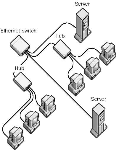
Replacing Hub with an Ethernet switch
If users in a department have high bandwidth needs, such as those running CAD or multimedia applications, consider replacing their workgroup hub with an Ethernet switch, or if the number of users is small, connect their stations directly to the main Ethernet switch.
Another use for Ethernet switches is to connect 100-Mbps Ethernet “islands” to an existing 10-Mbps Ethernet LAN. Simply use a 10/100-Mbps Ethernet switch with two ports to connect them.
You can also connect two LANs several kilometers apart by using two Ethernet switches, both having one 100BaseT port and one 100BaseFX port. Connect the switches to the LANs, and then connect a fiber-optic cable between the FX ports.
When purchasing Ethernet switches, make sure they have RMON agents built into each port, as this will considerably ease remote network troubleshooting.