The Real-time Transport Protocol (RTP) is a network protocol that provides end-to-end network transport functions suitable for applications transmitting real-time data, such as audio, video, or simulation data, over multicast or unicast network services.
In this article:
RTP Basics
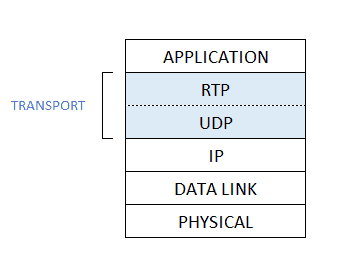
Real-time Transport Protocol (RTP) runs on top of UDP. Specifically, audio or video chunks of data, generated by the sending side of a multimedia application, are encapsulated in RTP packets, and each RTP packet is in turn encapsulated in a UDP segment.
Because RTP provides services like timestamps or sequence numbers, to the multimedia application, RTP can be viewed as a sublayer of the transport layer.
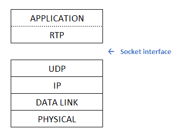
From the application developer’s perspective, however, RTP is not part of the transport layer but instead part of the application layer. This is because the developer must integrate RTP into the application. Specifically, for the sender side of the application, the developer must write code into the application which creates the RTP encapsulating packets; the application then sends the RTP packets into a UDP socket interface. Similarly, at the receiver side of the application, the RTP packets enter the application through a UDP socket interface; the developer therefore must write code into the application that extracts the media chunks from the RTP packets.
If an application incorporates RTP — instead of a proprietary scheme to provide payload type, sequence numbers or timestamps – then, the application will more easily interoperate with other networking applications. For example, if two different companies develop Internet phone software, and they both incorporate RTP into their product, there may be some hope that a user using one of the Internet phone products will be able to communicate with a user using the other Internet phone product.
It should be emphasized that RTP in itself does not provide any mechanism to ensure timely delivery of data or provide other quality of service guarantees; it does not even guarantee delivery of packets or prevent out-of-order delivery of packets. Indeed, RTP encapsulation is only seen at the end systems — it is not seen by intermediate routers. Routers do not distinguish between IP datagrams that carry RTP packets and IP datagrams that don’t.
RTP allows each source (for example, a camera or a microphone) to be assigned its own independent RTP stream of packets. For example, for a videoconference between two participants, four RTP streams could be opened: two streams for transmitting the audio (one in each direction) and two streams for the video (again, one in each direction). However, many popular encoding techniques — including MPEG1 and MPEG2 — bundle the audio and video into a single stream during the encoding process. When the audio and video are bundled by the encoder, then only one RTP stream is generated in each direction.
RTP packets are not limited to unicast applications. They can also be sent over one-to-many and many-to-many multicast trees. For a many-to-many multicast session, all of the senders and sources in the session typically send their RTP streams into the same multicast tree with the same multicast address. RTP multicast streams belonging together, such as audio and video streams emanating from multiple senders in a videoconference application, belong to an RTP session.
RTP Packet Header Fields
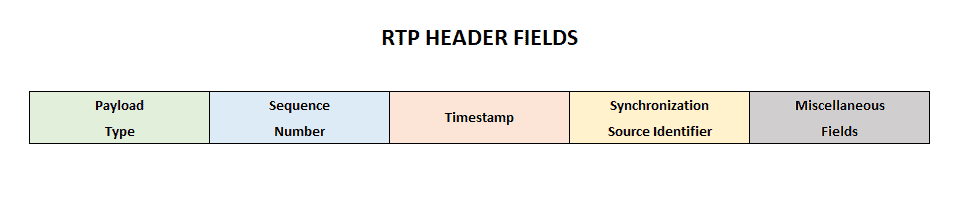
The four principal packet header fields are the payload type, sequence number, timestamp, and the source identifier.
Payload Type
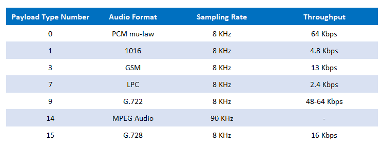
The payload type field in the RTP packet is seven-bits long. Thus 2^7 or 128 different payload types can be supported by RTP. For an audio stream, the payload type field is used to indicate the type of audio encoding (e.g., PCM, adaptive delta modulation, linear predictive encoding) that is being used. If a sender decides to change the encoding in the middle of a session, the sender can inform the receiver of the change through this payload type field. The sender may want to change the encoding in order to increase the audio quality or to decrease the RTP stream bit rate.
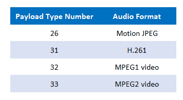
For a video stream the payload type can be used to indicate the type of video encoding (e.g., motion JPEG, MPEG1, MPEG2, H.231). Again, the sender can change video encoding on-the-fly during a session.
Sequence Number Field
The sequence number field is 16-bits long. The sequence number increments by one for each RTP packet sent, and may be used by the receiver to detect packet loss and to restore packet sequence. For example, if the receiver side of the application receives a stream of RTP packets with a gap between sequence numbers 86 and 89, then the receiver knows that packets 87 and 88 were lost. The receiver can then attempt to conceal the lost data.
Timestamp Field
The timestamp field is 32 bytes long. It reflects the sampling instant of the first byte in the RTP data packet. As we saw in the previous section, the receiver can use the timestamps in order to remove packet jitter introduced in the network and to provide synchronous playout at the receiver. The timestamp is derived from a sampling clock at the sender. As an example, for audio the timestamp clock increments by one for each sampling period (for example, each 125 usecs for a 8 KHz sampling clock); if the audio application generates chunks consisting of 160 encoded samples, then the timestamp increases by 160 for each RTP packet when the source is active. The timestamp clock continues to increase at a constant rate even if the source is inactive.
Synchronization Source Identifier (SSRC)
The SSRC field is 32 bits long. It identifies the source of the RTP stream. Typically, each stream in a RTP session has a distinct SSRC. The SSRC is not the IP address of the sender, but instead a number that the source assigns randomly when the new stream is started. The probability that two streams get assigned the same SSRC is very small.
RTP Control Protocol (RTCP)
Request For Comments 1889 also specifies RTCP, a protocol which a multimedia networking application can use in conjunction with RTP. The use of RTCP is particularly attractive when the networking application multicasts audio or video to multiple receivers from one or more senders.
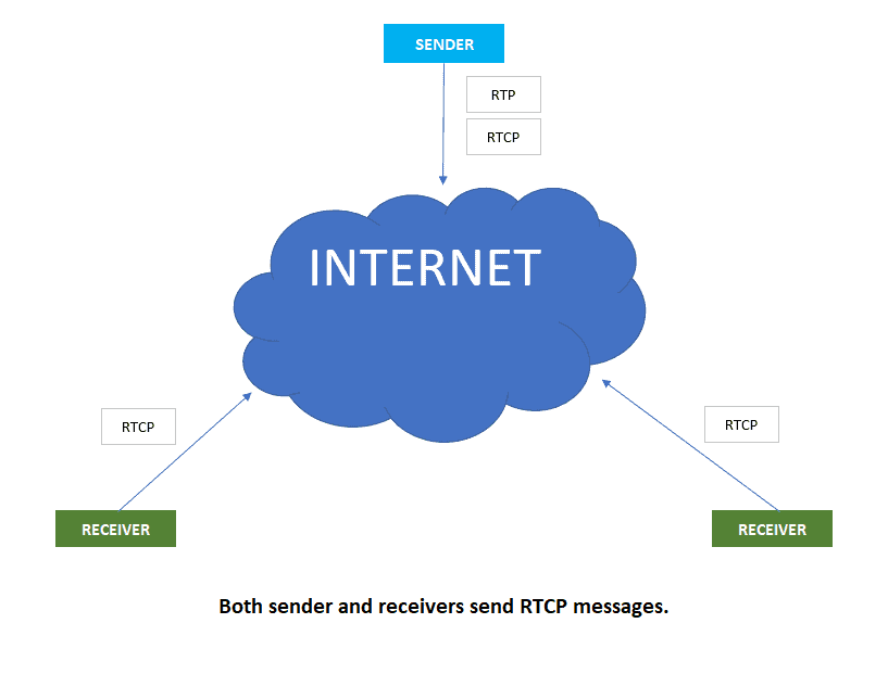
RTCP packets are transmitted by each participant in an RTP session to all other participants in the session. The RTCP packets are distributed to all the participants using IP multicast. For an RTP session, typically there is a single multicast address, and all RTP and RTCP packets belonging to the session use the multicast address. RTP and RTCP packets are distinguished from each other through the use of distinct port numbers.
RTCP packets do not encapsulate chunks of audio or video. Instead, RTCP packets are sent periodically and contain sender and/or receiver reports that announce statistics that can be useful to the application. These statistics include number of packets sent, number of packets lost and interarrival jitter. The RTP specification [RFC 1889] does not dictate what the application should do with this feedback information. It is up to the application developer to decide what it wants to do with the feedback information. Senders can use the feedback information, for example, to modify their transmission rates. The feedback information can also be used for diagnostic purposes; for example, receivers can determine whether problems are local, regional or global.
RTCP Packet Types
Receiver reception packets
For each RTP stream that a receiver receives as part of a session, the receiver generates a reception report. The receiver aggregates its reception reports into a single RTCP packet. The packet is then sent into multicast tree that connects together all the participants in the session. The reception report includes several fields, the most important of which are listed below.
- The SSRC of the RTP stream for which the reception report is being generated.
- The fraction of packets lost within the RTP stream. Each receiver calculates the number of RTP packets lost divided by the number of RTP packets sent as part of the stream. If a sender receives reception reports indicating that the receivers are receiving only a small fraction of the sender’s transmitted packets, the sender can switch to a lower encoding rate, thereby decreasing the congestion in the network, which may improve the reception rate.
- The last sequence number received in the stream of RTP packets.
- The interarrival jitter, which is calculated as the average interarrival time between successive packets in the RTP stream.
Sender report packets
For each RTP stream that a sender is transmitting, the sender creates and transmits RTCP sender-report packets. These packets include information about the RTP stream, including:
- The SSRC of the RTP stream.
- The timestamp and wall-clock time of the most recently generated RTP packet in the stream
- The number of packets sent in the stream.
- The number of bytes sent in the stream.
The sender reports can be used to synchronize different media streams within a RTP session. For example, consider a videoconferencing application for which each sender generates two independent RTP streams, one for video and one for audio. The timestamps in these RTP packets are tied to the video and audio sampling clocks, and are not tied to the wall-clock time (i.e., to real time). Each RTCP sender-report contains, for the most recently generated packet in the associated RTP stream, the timestamp of the RTP packet and the wall-clock time for when the packet was created. Thus, the RTCP sender-report packets associate the sampling clock to the real-time clock. Receivers can use this association in the RTCP sender reports to synchronize the playout of audio and video.
Source description packets
For each RTP stream that a sender is transmitting, the sender also creates and transmits source-description packets. These packets contain information about the source, such as e-mail address of the sender, the sender’s name and the application that generates the RTP stream. It also includes the SSRC of the associated RTP stream. These packets provide a mapping between the source identifier (i.e., the SSRC) and the user/host name.
RTCP packets are stackable, i.e., receiver reception reports, sender reports, and source descriptors can be concatenated into a single packet. The resulting packet is then encapsulated into a UDP segment and forwarded into the multicast tree.
RTCP Bandwidth Scaling
The astute reader will have observed that RTCP has a potential scaling problem. Consider for example an RTP session that consists of one sender and a large number of receivers. If each of the receivers periodically generate RTCP packets, then the aggregate transmission rate of RTCP packets can greatly exceed the rate of RTP packets sent by the sender. Observe that the amount of traffic sent into the multicast tree does not change as the number of receivers increases, whereas the amount of RTCP traffic grows linearly with the number of receivers. To solve this scaling problem, RTCP modifies the rate at which a participant sends RTCP packets into the multicast tree as a function of the number of participants in the session.
Observe that, because each participant sends control packets to everyone else, each participant can keep track of the total number of participants in the session.
RTCP attempts to limit its traffic to 5% of the session bandwidth. For example, suppose there is one sender, which is sending video at a rate of 2 Mbps. Then RTCP attempts to limit its traffic to 5% of 2 Mbps, or 100 Kbps, as follows. The protocol gives 75% of this rate, or 75 Kbps, to the receivers; it gives the remaining 25% of the rate, or 25 Kbps, to the sender. The 75 Kbps devoted to the receivers is equally shared among the receivers. Thus, if there are R receivers, then each receiver gets to send RTCP traffic at a rate of 75/R Kbps and the sender gets to send RTCP traffic at a rate of 25 Kbps. A participant (a sender or receiver) determines the RTCP packet transmission period by dynamically calculating the average RTCP packet size (across the entire session) and dividing the average RTCP packet size by its allocated rate.
In summary, the period for transmitting RTCP packets for a sender is
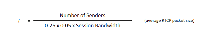
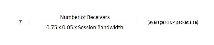
And the period for transmitting RTCP packets for a receiver is
H.323
H.323 is a standard for real-time audio and video conferencing among end systems on the Internet. As shown in Figure 6.4-7, it also covers how end systems attached to the Internet communicate with telephones attached to ordinary circuit-switched telephone networks. In principle, if manufacturers of Internet telephony and video conferencing all conform to H.323, then all their products should be able to interoperate and should be able to communicate with ordinary telephones. We discuss H.323 in this section, as it provides an application context for RTP. Indeed, we shall see below that RTP is an integral part of the H.323 standard.
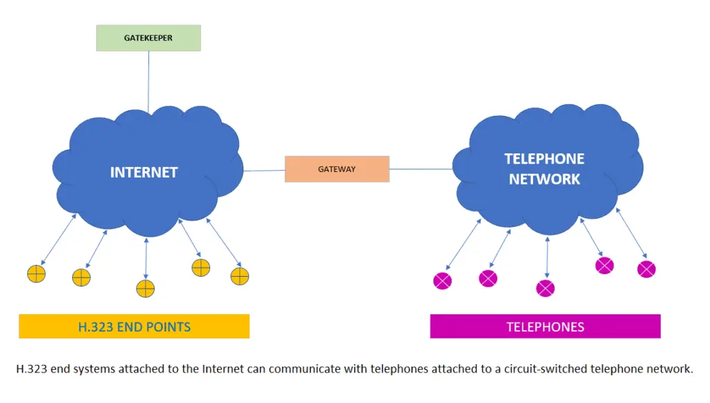
H.323 end points (a.k.a. terminals) can be stand-alone devices (e.g., Web phones and Web TVs) or applications in a PC (e.g., Internet phone or video conferencing software). H.323 equipment also includes gateways and gatekeepers. Gateways permit communication among H.323 end points and ordinary telephones in a circuit-switched telephone network. Gatekeepers, which are optional, provide address translation, authorization, bandwidth management, accounting and billing. We will discuss gatekeepers in more detail at the end of this section.
The H.323 is an umbrella specification that includes:
- A specification for how endpoints negotiate common audio/video encodings. Because H.323 supports a variety of audio and video encoding standards, a protocol is needed to allow the communicating endpoints to agree on a common encoding.
- A specification for how audio and video chunks are encapsulated and sent over the network. As you may have guessed, this is where RTP comes into the picture.
- A specification for how endpoints communicate with their respective gatekeepers.
- A specification for how Internet phones communicate through a gateway with ordinary Phones in the public circuit-switched telephone network.
Minimally, each H.323 endpoint must support the G.711 speech compression standard. G.711 uses PCM to generate digitized speech at either 56 kbps or 64 kbps. Although H.323 requires every endpoint to be voice capable (through G.711), video capabilities are optional. Because video support is optional, manufacturers of terminals can sell simpler speech terminals as well as more complex terminals that support both audio and video.
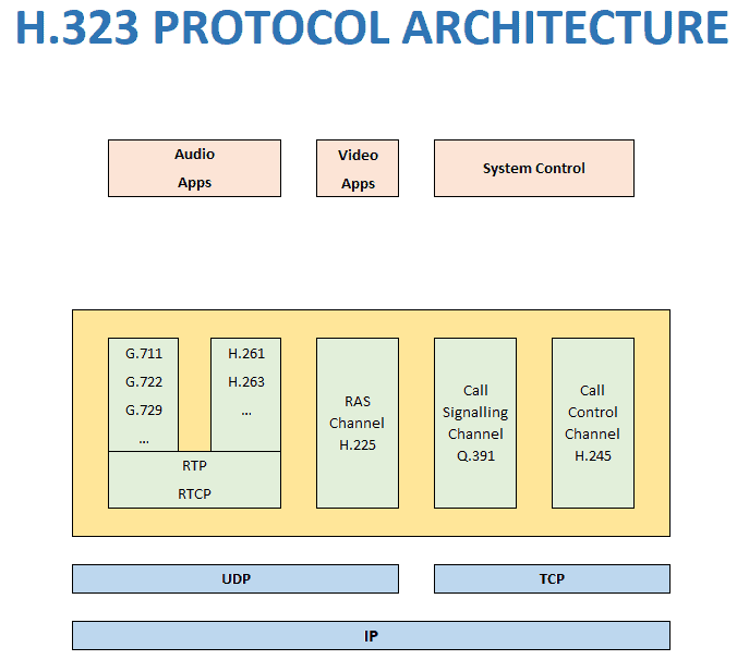
H.323 also requires that all H.323 end points use the following protocols:
- RTP – the sending side of an endpoint encapsulates all media chunks within RTP packets. Sending side then passes the RTP packets to UDP.
- H.245 – an “out-of-band” control protocol for controlling media between H.323 endpoints. This protocol is used to negotiate a common audio or video compression standard that will be employed by all the participating endpoints in a session.
- Q.931 – a signaling protocol for establishing and terminating calls. This protocol provides traditional telephone functionality (e.g., dial tones and ringing) to H.323 endpoints and equipment.
- RAS (Registration/Admission/Status) channel protocol – a protocol that allows end points to communicate with a gatekeeper (if gatekeeper is present).
Audio and Video Compression
The H.323 standard supports a specific set of audio and video compression techniques. Let’s first consider audio. As we just mentioned, all H.323 end points must support the G.711 speech encoding standard. Because of this requirement, two H.323 end points will always be able to default to G.711 and communicate. But H.323 allows terminals to support a variety of other speech compression standards, including G.723.1, G.722, G.728 and G.729. Many of these standards compress speech to rates that will pass through 28.8 Kbps dial-up modems. For example, G.723.1 compresses speech to either 5.3 kbps or 6.3 kbps, with sound quality that is comparable to G.711.
As we mentioned earlier, video capabilities for an H.323 endpoint are optional. However, if an endpoint does supports video, then it must (at the very least) support the QCIF H.261 (176×144 pixels) video standard. A video capable endpoint my optionally support other H.261 schemes, including CIF, 4CIF and 16CIF., and the H.263 standard. As the H.323 standard evolves, it will likely support a longer list of audio and video compression schemes.
H.323 Channels
When a end point participates in an H.323 session, it maintains several channels.
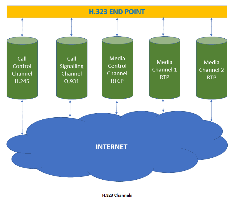
We see that an end point can support many simultaneous RTP media channels. For each media type, there will typically be one send media channel and one receive media channel; thus, if audio and video are sent in separate RTP streams, there will typically be four media channels. Accompanying the RTP media channels, there is one RTCP media control channel. All of the RTP and RTCP channels run over UDP. In addition to the RTP/RTCP channels, two other channels are required, the call control channel and the call signaling channel. The H.245 call control channel is a TCP connection that carries H.245 control messages.
Its principal tasks are (i) opening and closing media channels; and (ii) capability exchange, i.e., before sending media, endpoints agree on and encoding algorithm. H.245, being a control protocol for real-time interactive applications, is analogous to RTSP, which is a control protocol for streaming of stored multimedia. Finally, the Q.931 call signaling channel provides classical telephone functionality, such as dial tone and ringing.
Gatekeepers
The gatekeeper is an optional H.323 device. Each gatekeeper is responsible for an H.323 zone.
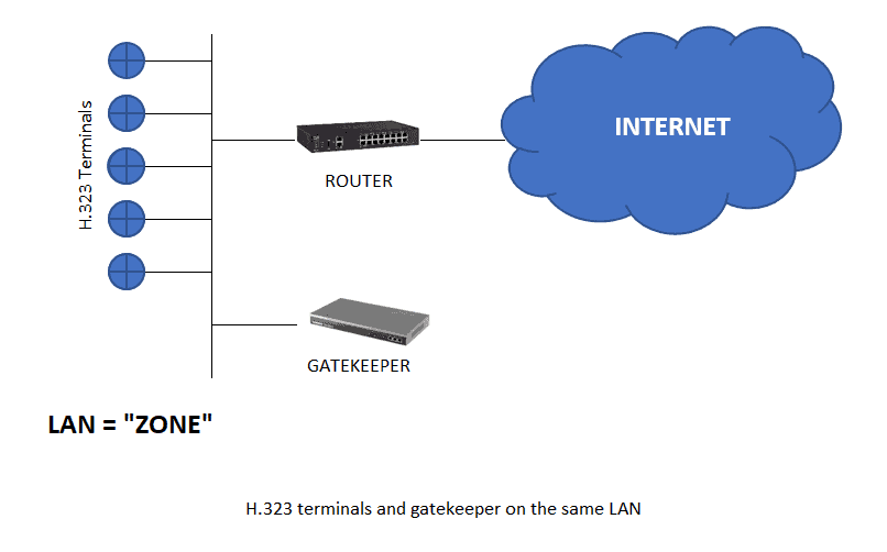
In this deployment scenario, the H.323 terminals and the gatekeeper are all attached to the same LAN, and the H.323 zone is the LAN itself. If a zone has a gatekeeper, then all H.323 terminals in the zone are required to communicate with it using the RAS protocol, which runs over TCP.
Address translation is one of the more important gatekeeper services. Each terminal can have an alias address, such as the name of the person at the terminal, the e-mail address of the person at the terminal, etc. The gateway translates these alias addresses to IP addresses. This address translation service is similar to the DNS service. Another gatekeeper service is bandwidth management: the gatekeeper can limit the number of simultaneous real-time conferences in order to save some bandwidth for other applications running over the LAN. Optionally, H.323 calls can be routed through gatekeeper, which is useful for billing.
H.323 terminal must register itself with the gatekeeper in its zone. When the H.323 application is invoked at the terminal, the terminal uses RAS to send its IP address and alias (provided by user) to the gatekeeper. If gatekeeper is present in a zone, each terminal in the zone must contact gatekeeper to ask permission to make a call. Once it has permission, the terminal can send the gatekeeper an e-mail address, alias string or phone extension for the terminal it wants to call, which may be in another zone. If necessary, a gatekeeper will poll other gatekeepers in other zones to resolve an IP address.