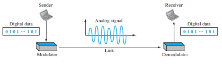
Digital-to-analog conversion is the process of changing one of the characteristics of an analog signal based on the information in digital data. The following image shows the relationship between the digital information, the digital-to-analog modulating process, and the resultant analog signal.
A sine wave is defined by three characteristics:
- amplitude
- frequency
- phase.
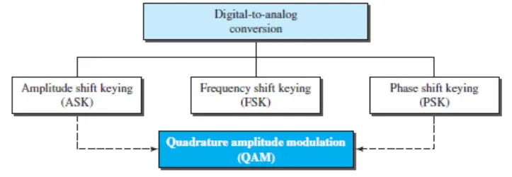
When we vary any one of these characteristics, we create a different version of that wave. So, by changing one characteristic of a simple electric signal, we can use it to represent digital data. Any of the three characteristics can be altered in this way, giving us at least three mechanisms for modulating digital data into an analog signal: amplitude shift keying (ASK), frequency shift keying (FSK), and phase shift keying (PSK). In addition, there is a fourth (and better) mechanism that combines changing both the amplitude and phase, called quadrature amplitude modulation (QAM). QAM is the most efficient of these options and is the mechanism commonly used today (see the image below).
In this article:
- Aspects of Digital-to-Analog Conversion
- Amplitude Shift Keying
- Frequency Shift Keying
- Phase Shift Keying
- Quadrature Amplitude Modulation
- References
Aspects of Digital-to-Analog Conversion
Before we discuss specific methods of digital-to-analog modulation, two basic issues must be reviewed: bit and baud rates and the carrier signal.
Data Element Versus Signal Element
Data element is the smallest piece of information to be exchanged, the bit.
A signal element is the smallest unit of a signal that is constant.
However, the nature of the signal element is a little bit different in analog transmission.
Data Rate Versus Signal Rate
We can define the data rate (bit rate) and the signal rate (baud rate) as we did for digital transmission. The relationship between them is
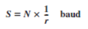
where N is the data rate (bps) and r is the number of data elements carried in one signal element. The value of r in analog transmission is r = log2 L, where L is the number of different signal elements. The same nomenclature is used to simplify the comparisons.
Bit rate is the number of bits per second. Baud rate is the number of signal elements per second. In the analog transmission of digital data, the baud rate is less than or equal to the bit rate.
Bandwidth
The required bandwidth for analog transmission of digital data is proportional to the signal rate except for FSK, in which the difference between the carrier signals needs to be added.
Carrier Signal
In analog transmission, the sending device produces a high-frequency signal that acts as a base for the information signal. This base signal is called the carrier signal or carrier frequency. The receiving device is tuned to the frequency of the carrier signal that it expects from the sender. Digital information then changes the carrier signal by modifying one or more of its characteristics (amplitude, frequency, or phase). This kind of modification is called modulation (shift keying).
Amplitude Shift Keying
In amplitude shift keying, the amplitude of the carrier signal is varied to create signal elements. Both frequency and phase remain constant while the amplitude changes.
Binary ASK (BASK)
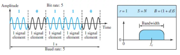
Although we can have several levels (kinds) of signal elements, each with a different amplitude, ASK is normally implemented using only two levels. This is referred to as binary amplitude shift keying or on-off keying (OOK). The peak amplitude of one signal level is 0; the other is the same as the amplitude of the carrier frequency. The following figure gives a conceptual view of binary ASK.
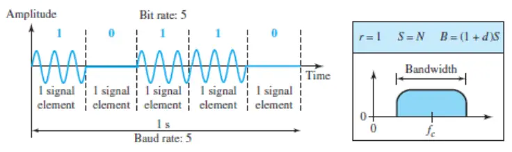
Bandwidth for ASK
The previous figure also shows the bandwidth for ASK. Although the carrier signal is only one simple sine wave, the process of modulation produces a nonperiodic composite signal.
This signal has a continuous set of frequencies. As we expect, the bandwidth is proportional to the signal rate (baud rate). However, there is normally another factor involved, called d, which depends on the modulation and filtering process. The value of d is between 0 and 1. This means that the bandwidth can be expressed as shown, where S is the signal rate and the B is the bandwidth.
B = (1 + d) x S
The formula shows that the required bandwidth has a minimum value of S and a maximum value of 2S. The most important point here is the location of the bandwidth.
The middle of the bandwidth is where fc, the carrier frequency, is located. This means if we have a bandpass channel available, we can choose our fc so that the modulated signal occupies that bandwidth. This is in fact the most important advantage of digital-to-analog conversion. We can shift the resulting bandwidth to match what is available.
Implementation
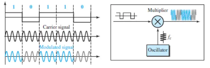
The complete discussion of ASK implementation is beyond the scope of this article. However, the simple ideas behind the implementation may help us to better understand the concept itself. The following figure shows how we can simply implement binary ASK.
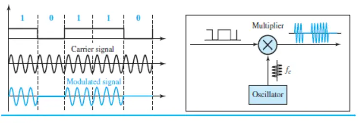
If digital data are presented as a unipolar NRZ digital signal with a high voltage of 1 V and a low voltage of 0 V, the implementation can be achieved by multiplying the NRZ digital signal by the carrier signal coming from an oscillator.
When the amplitude of the NRZ signal is 1, the amplitude of the carrier frequency is held; when the amplitude of the NRZ signal is 0, the amplitude of the carrier frequency is zero.
Frequency Shift Keying
In frequency shift keying, the frequency of the carrier signal is varied to represent data. The frequency of the modulated signal is constant for the duration of one signal element, but changes for the next signal element if the data element changes. Both peak amplitude and phase remain constant for all signal elements.
Binary FSK (BFSK)
One way to think about binary FSK (or BFSK) is to consider two carrier frequencies. In the following figure, we have selected two carrier frequencies, f1 and f2. We use the first carrier if the data element is 0; we use the second if the data element is 1. However, note that this is an unrealistic example used only for demonstration purposes. Normally the carrier frequencies are very high, and the difference between them is very small.
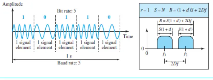
As the above figure shows, the middle of one bandwidth is f1 and the middle of the other is f2. Both f1 and f2 are Δf apart from the midpoint between the two bands. The difference between the two frequencies is 2Δf.
Bandwidth for BFSK
The same figure also shows the bandwidth of FSK. Again, the carrier signals are only simple sine waves, but the modulation creates a nonperiodic composite signal with continuous frequencies. We can think of FSK as two ASK signals, each with its own carrier frequency (f1 or f2). If the difference between the two frequencies is 2Δf, then the required bandwidth is
B = (1 + d) x S + 2Δφ
What should be the minimum value of 2Δf ? In the above figure, we have chosen a value greater than (1 + d )S. It can be shown that the minimum value should be at least S for the proper operation of modulation and demodulation.
Implementation
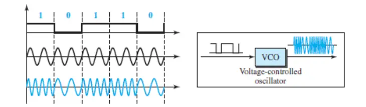
There are two implementations of BFSK: noncoherent and coherent. In noncoherent BFSK, there may be discontinuity in the phase when one signal element ends and the next begins. In coherent BFSK, the phase continues through the boundary of two signal elements. Noncoherent BFSK can be implemented by treating BFSK as two ASK modulations and using two carrier frequencies. Coherent BFSK can be implemented by using one voltage-controlled oscillator (VCO) that changes its frequency according to the input voltage. The next Figure shows the simplified idea behind the second implementation.
The input to the oscillator is the unipolar NRZ signal. When the amplitude of NRZ is zero, the oscillator keeps its regular frequency; when the amplitude is positive, the frequency is increased.
Multilevel FSK
Multilevel modulation (MFSK) is not uncommon with the FSK method. We can use more than two frequencies. For example, we can use four different frequencies f1, f2, f3, and f4 to send 2 bits at a time. To send 3 bits at a time, we can use eight frequencies.
And so on. However, we need to remember that the frequencies need to be 2Δf apart. For the proper operation of the modulator and demodulator, it can be shown that the minimum value of 2Δf needs to be S. We can show that the bandwidth is
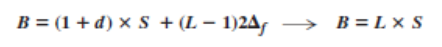
Note that MFSK uses more bandwidth than the other techniques; it should be used when noise is a serious issue.
Phase Shift Keying
In phase shift keying, the phase of the carrier is varied to represent two or more different signal elements. Both peak amplitude and frequency remain constant as the phase changes. Today, PSK is more common than ASK or FSK. However, we will see shortly that QAM, which combines ASK and PSK, is the dominant method of digital-to-analog modulation.
Binary PSK (BPSK)
The simplest PSK is binary PSK, in which we have only two signal elements, one with a phase of 0°, and the other with a phase of 180°. The next figure gives a conceptual view of PSK. Binary PSK is as simple as binary ASK with one big advantage – it is less susceptible to noise. In ASK, the criterion for bit detection is the amplitude of the signal; in PSK, it is the phase. Noise can change the amplitude easier than it can change the phase. In other words, PSK is less susceptible to noise than ASK. PSK is superior to FSK because we do not need two carrier signals. However, PSK needs more sophisticated hardware to be able to distinguish between phases.
Bandwidth
The above figure also shows the bandwidth for BPSK. The bandwidth is the same as that for binary ASK, but less than that for BFSK. No bandwidth is wasted for separating two carrier signals.
Implementation
The implementation of BPSK is as simple as that for ASK. The reason is that the signal element with phase 180° can be seen as the complement of the signal element with phase 0°. This gives us a clue on how to implement BPSK. We use the same idea we used for ASK but with a polar NRZ signal instead of a unipolar NRZ signal, as shown in the next figure. The polar NRZ signal is multiplied by the carrier frequency; the 1 bit (positive voltage) is represented by a phase starting at 0°; the 0 bit (negative voltage) is represented by a phase starting at 180°.
Quadrature PSK (QPSK)
The simplicity of BPSK enticed designers to use 2 bits at a time in each signal element, thereby decreasing the baud rate and eventually the required bandwidth. The scheme is called quadrature PSK or QPSK because it uses two separate BPSK modulations; one is in-phase, the other quadrature (out-of-phase).
The incoming bits are first passed through a serial-to-parallel conversion that sends one bit to one modulator and the next bit to the other modulator. If the duration of each bit in the incoming signal is T, the duration of each bit sent to the corresponding BPSK signal is 2T. This means that the bit to each BPSK signal has one-half the frequency of the original signal. The following figure shows the idea.
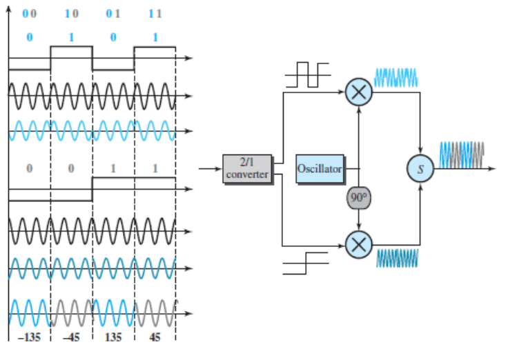
The two composite signals created by each multiplier are sine waves with the same frequency, but different phases. When they are added, the result is another sine wave, with one of four possible phases: 45°, −45°, 135°, and −135°. There are four kinds of signal elements in the output signal (L = 4), so we can send 2 bits per signal element (r = 2).
Constellation Diagram
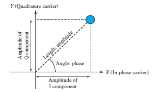
A constellation diagram can help us define the amplitude and phase of a signal element, particularly when we are using two carriers (one in-phase and one quadrature). The diagram is useful when we are dealing with multilevel ASK, PSK, or QAM. In a constellation diagram, a signal element type is represented as a dot. The bit or combination of bits it can carry is often written next to it.
The diagram has two axes. The horizontal X axis is related to the in-phase carrier; the vertical Y axis is related to the quadrature carrier. For each point on the diagram, four pieces of information can be deduced. The projection of the point on the X axis defines the peak amplitude of the in-phase component; the projection of the point on the Y axis defines the peak amplitude of the quadrature component.
The length of the line (vector) that connects the point to the origin is the peak amplitude of the signal element (combination of the X and Y components); the angle the line makes with the X axis is the phase of the signal element. All the information we need can easily be found on a constellation diagram. The next figure shows a constellation diagram.
Quadrature Amplitude Modulation
PSK is limited by the ability of the equipment to distinguish small differences in phase.
This factor limits its potential bit rate. So far, we have been altering only one of the three characteristics of a sine wave at a time; but what if we alter two? Why not combine ASK and PSK? The idea of using two carriers, one in-phase and the other quadrature, with different amplitude levels for each carrier is the concept behind quadrature amplitude modulation (QAM).
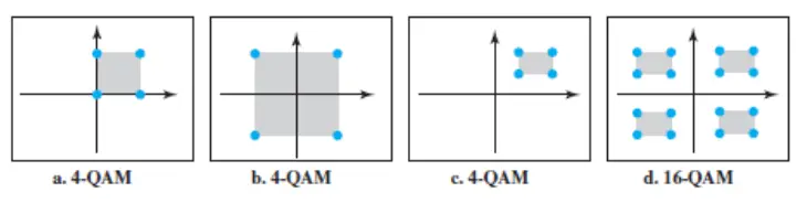
The possible variations of QAM are numerous. The next figure shows some of these schemes. The first diagram of image (a) shows the simplest 4-QAM scheme (four different signal element types) using a unipolar NRZ signal to modulate each carrier. This is the same mechanism we used for ASK (OOK). Part b shows another 4-QAM using polar NRZ, but this is exactly the same as QPSK. Part c shows another QAM-4 in which we used a signal with two positive levels to modulate each of the two carriers. Finally, part d shows a 16-QAM constellation of a signal with eight levels, four positive and four negative.
Bandwidth for QAM
The minimum bandwidth required for QAM transmission is the same as that required for ASK and PSK transmission. QAM has the same advantages as PSK over ASK.
To better understand this subject, we have written a specific article on QAM. You can read it here: What is Quadrature Amplitude Modulation?
References
This article was based on the book “Data Communications and Networking, 2013, B. Forouzan“. To delve deeper into the topic, you can purchase this same book on Amazon.
See also: